Slant/Fin VSPH-180 User Manual
Page 6
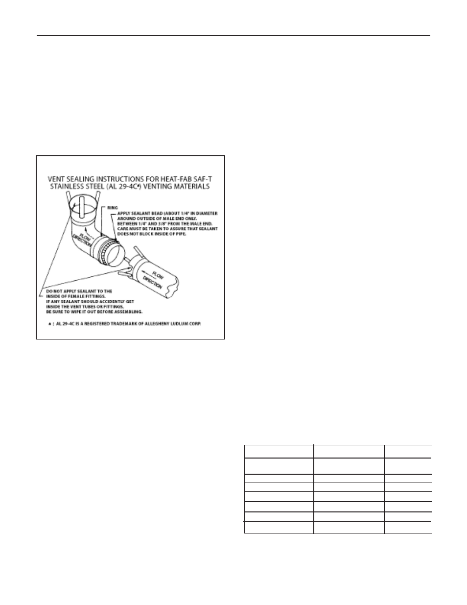
When joining the various components of the above listed
vent systems, the manufacturers’ instructions should be
closely followed to insure proper sealing. Use sealant speci-
fied by vent system manufacturer for sealing of pipe and fit-
tings. See Figure 4 for proper application of vent pipe sealing
for Saf-T vent system by Heat-Fab, Inc. All vent connections
must be liquid and pressure tight. Flue vent system CANNOT
be cut to length. Consult manufacturer’s instructions. For Heat-
Fab system, use slip joint connector to adjust pipe lengths
dimensions.
DO NOT use plastic or galvanized flue pipe.
AIR INTAKE PIPE MATERIAL
3” PVC Schedule 40 or galvanized steel materials are rec-
ommended.
All joints must be sealed using appropriate sealants.
FLUE AND AIR INTAKE RESTRICTIONS
1. Maximum allowed equivalent flue and air intake length for
different flue systems at different altitudes are given in the
tables on page 7.
2. Equivalent of flue or air intake length is sum of the
straight pipe lengths and equivalent length of elbows as
shown in the table on this page.
3. The vent termination is in addition to the allowed equiva-
lent lengths.
4. Minimum flue length is 2 feet.
5. Flue length restriction is for both direct and non-direct
vent installations.
EXAMPLE: Boiler model VSPH-180 is to be installed at sea
level. The combustion air is provided by air intake piping
directly to the boiler (direct-vent installation). Flue piping
includes 2 elbows and using Heat-Fab system. Air intake is
PVC and includes 3 elbows.
Maximum straight flue length would be 30-2x3=24 feet.
Maximum straight air intake pipe would be 40-3x5=25 feet.
If the air for combustion were taken from the boiler room
(non-direct vent installation), still the maximum straight flue
length would be 24 feet.
6.
All Victory VSPH boilers are equipped with a built-in
condensation drain and trap. The trap loop must be
filled with water. DO NOT operate the boiler without
filling the trap with water to prevent flue gas discharge
into space. The drain should extend to a floor drain or
to a container which may require emptying periodically.
7.
The horizontal vent pipe must be sloped upward from
the boiler at a pitch of at least
1
⁄
4
" per 1 foot of run, so
that the condensate from the vent system runs to the
drain trap.
8.
The horizontal vent pipes must be supported with pipe
straps at intervals no greater than indicated by vent
pipe manufacturer’s instructions. The vertical portion
vent pipe also must be supported per manufacturer’s
instructions. Support air intake piping in the same
manner as the vent pipes.
9.
Minimum clearances of vent pipes from combustible
constructions must be maintained (see Page 4). Main-
tain minimum 1" clearance between vent pipes and
PVC air intake pipes.
10.
Common venting with other appliances or another
VSPH boiler is not allowed.
11.
DO NOT install a vent damper or similar devices in
vent system or on the boiler.
12.
Do not insulate venting system.
V
ICTORY VSPH Models
6
Figure: 4
Vent Sealing Instructions
(Consult vent manufacturer’s instructions.)
Heat-Fab, Inc.
Saf-T Standard
3
elbow
Heat-Fab, Inc.
Saf-T, tight radius elbow
6
ProTech System, Inc.
FasNseal
6
Flex-L International, Inc.
StaR-34
6
Z-Flex, Inc.
Z-Vent
6
N/A
PVC, Schedule 40
5
N/A
Galvanized steel
6
Manufacturer
Type/System
Equivalent
Length (Feet)
Equivalent Length of Various 90-Degree Elbows