Slant/Fin VSPH-180 User Manual
Page 18
V
ICTORY VSPH Models
18
2. Power Connection
A. Remove electrical junction box cover.
B. Hot connection lead is black. Neutral connection lead is white.
Proper polarity is important for VSPH boilers. Reversed
polarity will cause system lockout and the power LED will
flash continuously.
C. Connect ground wire to ground screw inside the junction box.
D. Replace junction box cover.
THERMOSTAT CONNECTIONS
Install thermostat on an inside wall and away from any heat
sources, sunshine and drafts. Thermostat wires must be connect-
ed to terminals block on boiler. See wiring diagram Figure 13a.
Thermostat heat anticipator: For a non-zoned system set thermo-
stat heat anticipator to 0.4 Amps, for zoned system set to match
power requirements of zone valves or relays. Refer to manufactur-
er’s instructions and specifications. Also see instructions with ther-
mostat.
MULTI ZONING
For multiple zoning, either zone valves or circulators maybe used.
For zone valve system see Figure 14.
For pump zoning system see Figure 15 and Figure 16.
DO NOT use boiler transformer to power external accessories like
zone valve and relays, overload and/or burned-out transformer
and boiler malfunction can result. Use separate transformer to
power such components. For pump zoning system, remove boiler
circulator wire connector from P5 of electronic boiler control (See
Figure 13b).
WATER PIPING
Always follow good piping practices. Observe minimum 1" clear-
ance to combustibles around all uninsulated hot water pipes or
when openings around pipes are not protected by non-com-
bustible materials.
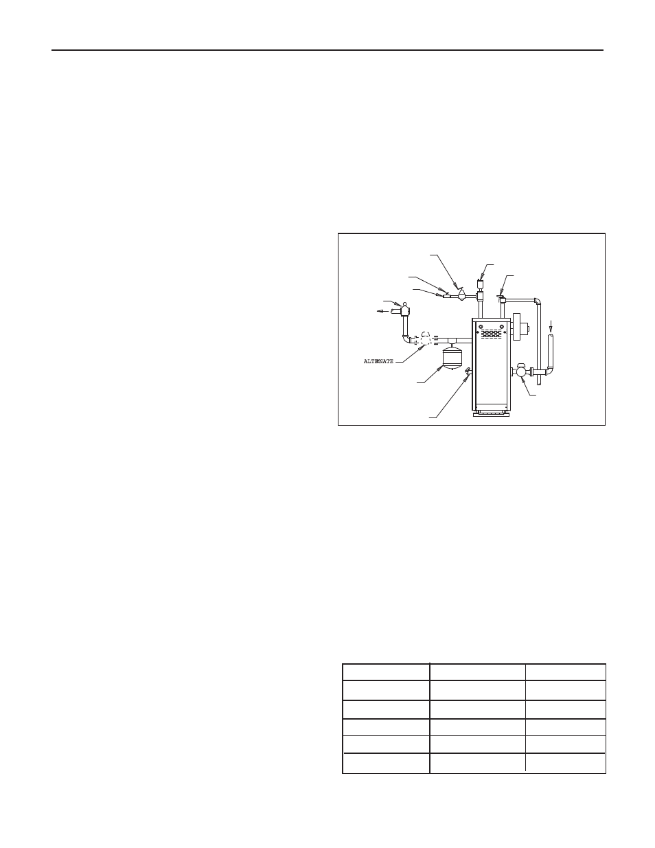
On a hot water boiler installed above radiation level, the boiler
must be provided with a low water cutoff device at the the time of
installation by the installer (see Figure 17 for piping arrangement).
The low water cutoff must be wired in series with rollout safety
switch and Aquastat (limit control). See wiring diagram Figure
13a.
1
1.. Supply and Return
For tapping sizes see dimensions on page 2. Shut-off valves
are recommended.
2
2.. Circulating Systems
Victory VSPH boilers are equipped with a water circulating
pump mounted to the return water connection on the boiler. This
pump location is appropriate for most installations. It may be
desired and proper to locate this pump to the alternate location
shown in Figure 17, especially when applied to larger systems
using high-head pumps.
When the pump is removed there is a 1
1
⁄
2”
FPT tapping that the
return pipe may be attached to.
At one month intervals after the last call for heat, the circulator
will be energized for 30 seconds. Short operation after long term
idle periods prevent damage of the pump from sedimentation.
3
3.. Radiant Floor, Low Water Temperature and large water
volume systems
A boiler by-pass loop, three way valve arrangement, or
primary secondary pumping (with a boiler loop) must be
used to provide a minumum 130˚ return water temperature
to the boiler. This will prevent condensation on the cast-iron
sections that can result in improper operation of the boiler.
4
4.. Air control system
Diaphragm type compression tank is used to control system
pressure. It must be installed at the boiler or between boiler
and supply main pump(s).
An automatic air vent is used to remove air from the system
in Figure 17. If system pressure needs further control, add
an additional tank in parallel with original tank or install a
larger capacity tank. Use appropriate size tank for volume of
water in system. See chart for boiler’s volume.
Model
Pounds
Gallons
VSPH-60
24.75
3.0
VSPH-90
32.00
3.8
VSPH-120
39.25
4.7
VSPH-150
46.50
5.6
VSPH-180
53.75
6.4
Boiler Water Content
GATE VALVE
GATE VALVE
FACTORY
FACTORY
CIRCULATOR
CIRCULATOR
LOCATIO N
LOCATIO N
3/4"
PRESSURE
3/4"
PRESSURE
RELIEF VALVE
RELIEF VALVE
AIR VE
NT
AIR VE
NT
RETURN
RETURN
SUPPLY
SUPPLY
EXPANSIO N
EXPANSIO N
TANK
TANK
ALTERNATE
CIRCULATOR
CIRCULATOR
LO
LO CAT
CATIO N
IO N
FLO W CONTROL
FLO W CONTROL
VALVE
VALVE
W ATER
FEED
W ATER
FEED
PRESSURE
PRESSURE
REDUCING
REDUCING
(FILL)VALVE
(FILL)VALVE
DRAIN COCK
DRAIN COCK
Figure 17. Piping arrangement