SilentKnight IPGSM-4G User Manual
Page 6
IPGSM-4G Commercial Fire Communicator – Installation and Setup Guide
– 4 –
4. Connect the LED Display board to its connector, then slide the board into the mounting rails. (Yellow LED and
Buzzer are on top.)
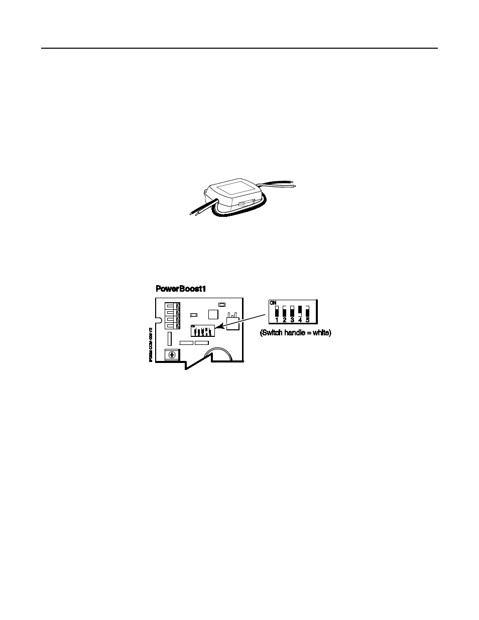
5. Carefully remove the packaging material that surrounds the PowerBoost1.
6. Mount the PowerBoost1 on the three unused standoffs. Use the two metal screws and lock washers to fasten
the left side of the circuit board. Ensure the lock washers are located between the circuit board and the head
of the two metal screws. The right side of the board just snaps in place on the upper right standoff.
7. Mount the Wall Outlet Box to an un-switched facility power outlet and run a conduit to the cabinet.
8. In this step DO NOT plug the transformer in. Route wire (minimum 18AWG) from the transformer,
through the conduit and into the cabinet. Pass the wires through the Ferrite Filter, then loop the wires back
through again making a loop. Connect the wires to the PowerBoost1 AC terminals.
9. Connect and route 16AWG insulated wire from facility power ground (typically a cold water pipe) to the cabi-
net's ground post. Ensure all ground connections are tight.
10. Connect the Ethernet cable and the Telco 1 and Telco 2 lines. If you choose to use an optional Cabinet Tam-
per Switch (if the fire panel supports it) mount and wire it.
11. Verify the PowerBoost1 DIP switches are configured as shown below.
12. Ensure the following:
•
LED Display board is fully seated.
•
All wiring terminals and connectors are tight.
•
All wiring has been completed and secured with cable ties.
13. Install the battery (not supplied). Plug the power transformer in, and attach the battery cable.