Step 4 – mount and wire – SilentKnight IPGSM-4G User Manual
Page 5
IPGSM-4G Commercial Fire Communicator – Installation and Setup Guide
– 3 –
STEP 3 – Determine the Signal Strength and Select a Location
IMPORTANT - Do Not mount this device outdoors.
RF Exposure
Warning - The internal or external antenna(s) used by this product must be installed to provide a
separation distance of at least 7.8 in. (20 cm) from all persons and must not be co-located or operat-
ing in conjunction with any other antenna or transmitter except in accordance with FCC multi-
transmitter product procedures.
When choosing a suitable mounting location, understand that signal strength is very important for proper operation.
For most installations using the supplied antenna, mounting the unit as high as practical, and avoiding large metal
components provides adequate signal strength for proper operation.
In this procedure you will use the Communicator to determine signal strength in order to find a suitable mounting loca-
tion.
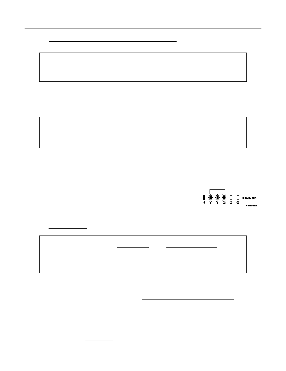
Note: If the SIM is already activated, the RSSI signal strength indicators will indicate signal strength.
If the SIM has not been activated, the firmware in the communicator enables it to communicate with
the cellular network towers (without the SIM being activated) so that signal strength measurements
can be determined. In this case, you can display the signal strength by simultaneously pressing the
TEST
/
REGISTRATION and MODE switches.
1. For this procedure you will need a fully charged 12V battery.
2. Attach the Antenna Mounting Adapter, RF cable, and Antenna (see illustration on page 5).
3. Temporarily wire the battery's negative [–] terminal to TB1–4 on the communicator, then wire the battery's
plus [+] terminal to TB1–2 on the communicator. Wait about one minute for the communicator to initialize.
4. Position the assembly near a suitable mounting position and observe the RSSI display.
5. Look for a mounting position that yields at least 3 bars lit solid. For optimal
performance 4 or 5 bars are better.
6. Verify the signal strength remains steady for a few minutes, then mark that
mounting position. Disconnect the battery.
STEP 4 – Mount and Wire
•
For UL compliant installations, refer to the topic on
UL Compliance
in this manual.
•
For UL compliant installations, the Telco line wiring and the Power Transformer wiring must be
routed through conduit.
•
For Dry/Indoor use only.
•
Unless otherwise specified, use 18AWG.
•
Additional cabinet wiring may be routed through conduit if desired.
This communicator comes partially assembled with all the components mounted except the external Antenna, LED Dis-
play board, and PowerBoost1. To protect certain components on the PowerBoost1, it is shipped un-mounted. All inter-
nal wiring is complete.
Note: Refer to the diagram on page 5, and to the Wiring Diagram on the inside of the back cover of this man-
ual for wiring and component identification.
1. Remove knockouts from cabinet to accommodate the power input wires, and wiring to the fire panel. Then
mount the cabinet securely to the wall using 4 screws or bolts. Use mounting screws or bolts that are suitable
for the material being anchored to.
2. Ensure the cabinet door lock is installed.
3. Install the two plastic mounting rails for the LED Display board. They simply snap into the back plate holes.