SeaLand 8100 Series MasterFlush Installation User Manual
Page 8
8
5 . Plan flush switch panel location so that electrical connections
and wires cannot get wet .
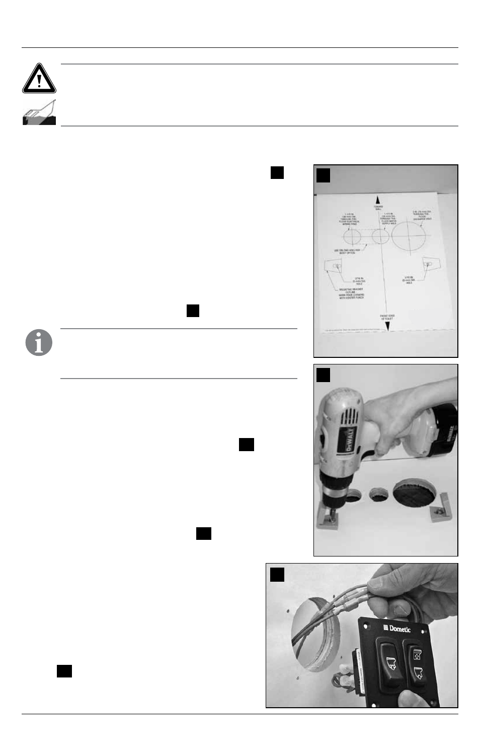
6 . Use MasterFlush 8100 series toilet wall switch template to
mark location of fastener and access holes for wall switch
panel . Drill 2 .75 in . (70 mm) diameter hole (fig .
9
) .
7 . With electrical power off, route 12-gauge or larger stranded
copper wire (according ABYC recommendations) from circuit
breaker or fuse to wall switch, and from wall switch to toilet .
Connect wires to appropriate leads attached to back of wall
switch panel with crimp-style wire connectors . (For complete
wiring options, refer to wiring diagrams (pp . 11-12) .
8 . Fasten wall switch panel to wall (fig .
9
) .
9 . Route wall switch panel wiring to toilet through
access hole in floor . Route ground connection
wire to toilet . (Provide extra wiring at toilet to
easily remove toilet from mounting brackets for
future maintenance or service .) Make final wiring
connections .
10 . Route water supply and discharge plumbing to
toilet according to system requirements (Section
4.2) . Provide extra water supply and discharge
hose lengths to assure easy connection to toilet
(fig .
13
, page 9) .
Dometic 8100 Series MasterFlush Toilet
Installation
Caution! Hazard of Flooding
If toilet uses raw water for flushing at ANY time, a raw water pump controlled by an automatically operat-
ing demand switch MUST NOT be installed . If the onboard water valve or any plumbing connections
were to leak, the automatically operated pump would start and could flood the boat . Failure to comply
with this warning can cause loss of property and life .
5.3
Toilet system with through-the-floor connections
1 . Place floor mounting template in desired location (fig .
7
) .
For optimal user comfort, make sure walls or other interior
fixtures are at least 11 in . (279 mm) away from centerline of
template .
2 . Center punch all holes and mounting bracket corners
through template .
3 . Remove template from floor . Drill all access and fastener
holes as indicated on template . DO NOT drill mounting
bracket corners .
4 . With long hex-head screws from toilet floor bracket kit,
fasten floor brackets with 3/8 in . (10 mm) socket wrench,
using corner marks as guides (fig .
8
) .
7
8
9
Note
Do not completely tighten hex-head screws to floor – allow
brackets to slightly slide . Brackets will tighten when fastening
toilet to brackets .