Replacement parts, Heating component functions, Optional furnace control board connections – Reznor R6GI Unit Installation Manual User Manual
Page 25: Connections, Table, Table 9, To determine fault condition
25
Table 10
Table 9
REPLACEMENT PARTS
Replacement parts are available through all Nordyne
distributors. Please have the complete model and serial
number of the unit when ordering replacement parts.
Electrical:
• Blower Control Boards
• Pressure Switches
• Compressors
• Reactor
• Contactors
• Relays
• Gas Valves
• Temperature Limit Switches
• Ignition Control Boards
• Thermistors
• Ignitors/Flame Sensors
• Thermostats
• Inverters
• Transformers
Motors:
• Blower Motor
• Fan Motor
• Inducer Blower Motor
Components:
• Blower Assembly
• Electronic Expansion Valves
• Burner Manifold
• Fan Grille
• Burners/Orifices
• Filter/Driers
• Cabinet Panels
• Gaskets
• Coil
• Heat Exchanger
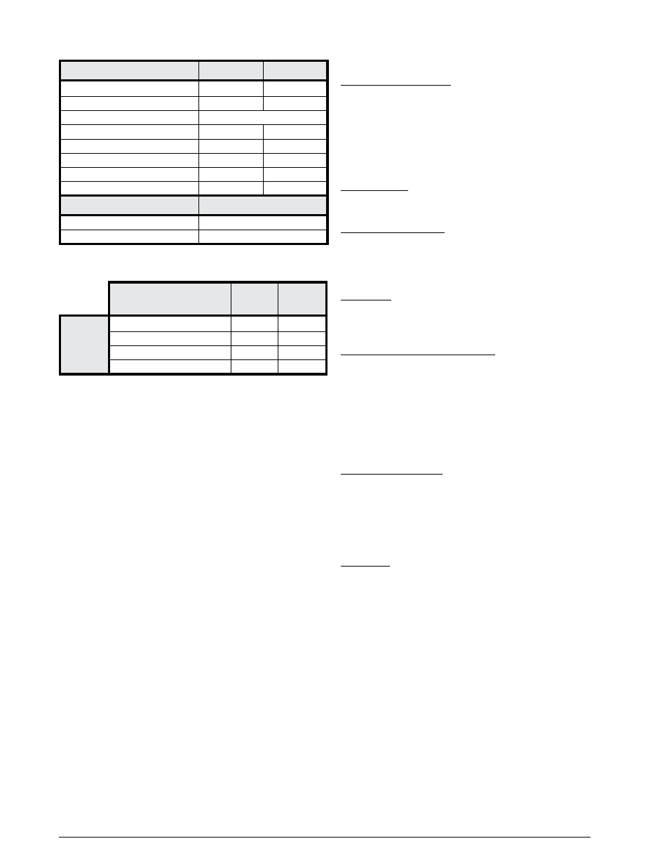
Table 9. Furnace Control Board Fault Conditions
DIAGNOSTIC
DESCRIPTION
GREEN
LED
RED
LED
VARIABLE
SPEED
FURNACES
Control Fault (No Power)
Off
Off
Normal Operation
On
On
Motor Fault
On
Flash
Communications Fault
Flash
Flash
DIAGNOSTIC DESCRIPTION
GREEN LED
RED LED
Control Fault (No Power)
Off
Off
L1/Neutral Polarity Fault
Flash
Flash
1 Hour Lockout
Alternating Flash
Normal Operation
On
On
Pressure Switch Closed Fault
On
Flash
Pressure Switch Open Fault
Flash
On
Open Limit Switch Fault
Flash
Off
Motor Fault
On
Off
DIAGNOSTIC DESCRIPTION
YELLOW LED
Low Flame Sensor Signal
Continuous Flash
Flame Present
On
Table 10. Motor Control Board Fault ConditionS
HEATING COMPONENT FUNCTIONS
Flame Roll-Out Control - The flame roll-out control acts to
verify that the burner flame is being drawn into the heat
exchanger tubes. If the burner flame is not being drawn
into the heat exchanger tubes, the roll-out control will
open within several seconds and the integrated control
diagnostic light will flash one time. The circulating air
blower will continue to operate while the flame roll-out
control is open. See
Flame Sensor - The flame sensor acts to prove that flame
has carried over from the ignitor to the left-most burner. If
no flame is sensed, the unit will be shut down automatically.
Dual Pressure Switch - The dual pressure switch verifies
that the inducer motor is drawing the combustion gases
through the heat exchanger tubes and venting the
gases through the vent system for both high and low fire
conditions.
Gas Valve - The gas valve controls the flow of gas to the
burners in both low and high fire. When the gas valve is
energized it automatically opens and regulates the gas
pressure in the manifold.
Over-Temperature Limit Control - The over-temperature
limit control prevents the air temperature leaving the unit
from exceeding the maximum outlet air temperature. If the
limit opens, the integrated control diagnostic will flash one
time. The circulating air blower will continue to operate
while the over-temperature limit control is open.
OPTIONAL FURNACE CONTROL BOARD
CONNECTIONS
Electronic Air Cleaner - The furnace control board provides
output terminals for an optional electronic air cleaner
(EAC) that can be installed in the return air duct of your
system. THE EAC output is energized any time the HEAT
or COOL blower speed is energized. Control ratings are
1.0 Amp. @ 240 VAC. Output connections are made via
board terminals labeled EAC and NEUTRAL.
Humidifier - The furnace control board provides output
terminals for an optional humidifier (HUM) that can be
installed on your system. The HUM output is energized
any time the furnace inducer motor is energized. Control
ratings are 1.0 Amp. @ 240 VAC. Output connections are
made via board terminals labeled HUM and NEUTRAL.