Heat / cool thermostat, Checking heat anticipator settings, Cooling configurations – Reznor R6GI Unit Installation Manual User Manual
Page 12: Heating configurations, Cooling configurations heating configurations
12
Figure 6
Table 4
Table 3
on an outside wall or any other location where its
operation may be adversely affected by radiant heat from
fireplaces, sunlight, or lighting fixtures, and convective
heat from warm air registers or electrical appliances.
Refer to the thermostat manufacturer’s instruction sheet
for detailed mounting information.
Heat / Cool Thermostat
2-Stage Heat / 2-Stage Cool Thermostat (Recommended):
For highest efficiency a 2 Stage Heating/Cooling
thermostat is recommended for this unit. A 2 Stage Cool
thermostat is required for control of the special variable
speed compressor. A 2 Stage Heat thermostat will allow
the gas heat to operate at a more efficient low heat
condition until there is a demand for higher heat output
to the conditioned space.
Single Stage Heat / 2 Stage Cool Thermostat (Optional):
A 2 Stage Cool thermostat is required for control of the
special variable speed compressor. A single stage Heat
thermostat can be used in conjunction with the automatic
heat staging jumper on the ignition control board. The heat
staging function will automatically move the unit into high
heat operation at the time interval selected:
OFF = Low heat operation only and ON = 10 minute delay
from low to high heat mode. See
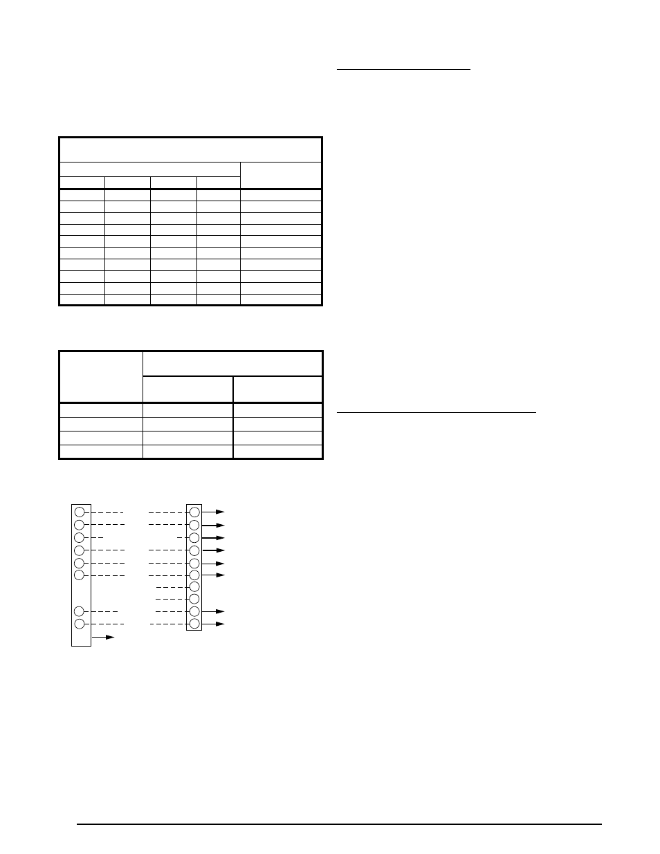
Connect the Red, Yellow, Green, Blue, White, and Brown
(optional) low voltage thermostat wires to terminals R,
Y1 (1st Stage Cool), G, Y2 (2nd Stage Cool), W1 (1st
Stage Heat), & W2 (2nd Stage Heat-optional) on both
the thermostat sub-base and unit low voltage terminal
board. The C terminal (Black wire), is the 24V common
wire required on some thermostat models. See
.
Checking Heat Anticipator Settings
• Add the current draw of the system components.
OR
• Measure the current flow on the thermostat
R-W circuit
after the circulating blower motor has started. Set the heat
anticipator according to the thermostat manufacturer’s
instructions for heat anticipator settings.
Cooling Configurations
This unit is designed to operate 5 stages of cooling
controlled by any standard 2-stage thermostat. The
connection between Y1 on the thermostat and Y1 on
the unit terminal strip energizes first stage cooling. The
connection bewteen Y2 on the thermostat and Y2 on the
unit terminal strip energizes second stage cooling. The
additional stages are controlled by run time and outdoor
temperature. See
.
Heating Configurations
This gas pack is factory configured for two stage gas
heating operation with a two stage heating thermostat.
Connect the low voltage thermostat White & Brown wires
to W1 & W2, between the unit low voltage terminal board
and thermostat sub-base. See
.
To operate with a single stage heat thermostat, only
connect the low voltage thermostat White wire between
W1 on the unit low voltage terminal board and thermostat
sub-base. Reposition the automatic heat staging jumper
located on the ignition control module from OFF to ON
to set a 10 minute time delay before the gas furnace will
automatically move to high heat operation.
Table 4. Thermostat Wire Gauge
THERMOSTAT
WIRE GAUGE
RECOMMENDED T-STAT WIRE
LENGTH (UNIT TO T-STAT)
2-WIRE
(HEATING)
5-WIRE
(HEATING/COOLING)
24
55
25
22
90
45
20
140
70
18
225
110
COPPER WIRE SIZE — AWG
(1% VOLTAGE DROP)
SUPPLY WIRE LENGTH-FEET
SUPPLY CIRCUIT
AMPACITY
200
150
100
50
6
8
10
14
15
4
6
8
12
20
4
6
8
10
25
4
4
6
10
30
3
4
6
8
35
3
4
6
8
40
2
3
4
6
45
2
3
4
6
50
2
3
4
6
55
1
2
3
4
60
Wire Size based on N.E.C. for 60° type copper conductors.
Table 3. Copper Wire Size
Figure 6. Two Stage Heating / Two Stage
Cooling Configuration
TERMINAL STRIP
THERMOSTAT
R
G
C
W2
W1
RED
YELLOW
GREEN
BLACK
BLUE
WHITE
NOTE:
For use with compatible thermostats only. Refer to the thermostat manual for
detailed installation and programming instructions.
C
L
R
W1
G
Y2
Y1
Y1
Y2
W2
BROWN
L
OPTIONAL - SEE NOTE
O
E
NOT USED
NOT USED
Blower (Auto or Continuous ON)
24VAC (Common)
Diagnostics
1
ST
Stage Heat
24VAC
2
ND
Stage Cool
To Blower Control Board (Optional)
1
ST
Stage Cool
2
ND
Stage Heat
DEHUM