Troubleshooting - cooling mode, Diagnostic display, Instrumentation – Reznor R6GI Unit Installation Manual User Manual
Page 24: Low ambient cooling, Troubleshooting - heating mode, Troubleshooting - cooling mode diagnostic display
24
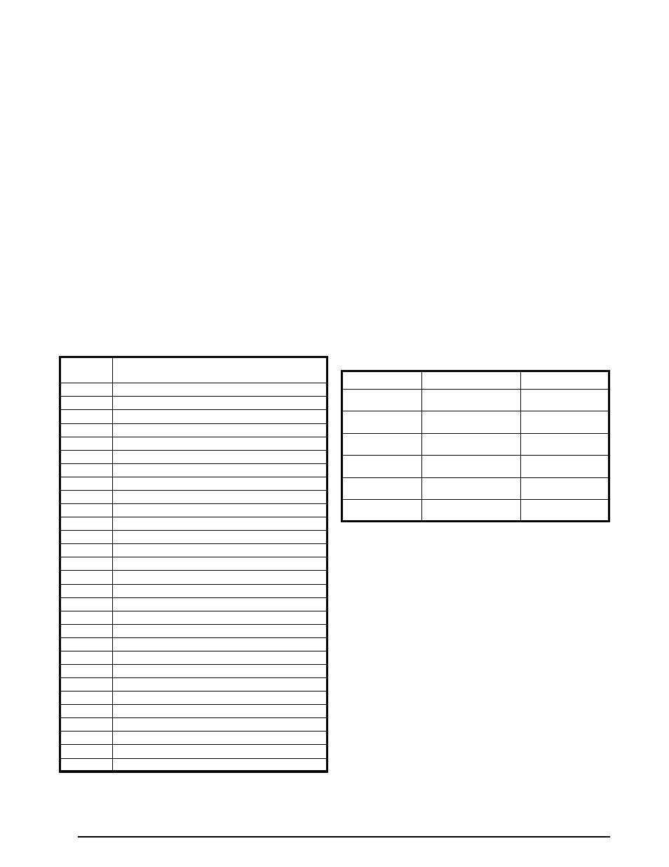
Table 8
Table 7
DISPLAY
CODE
INDICATION
01
Inverter Power Module Overcurrent
02
General Inverter Drive Fault
03
High Compressor Current
04
Current Sampling Error (Inverter)
05
High Inverter Heat Sink Temperature
06
High DC Bus Voltage (Inverter)
07
Low DC Bus Voltage (Inverter)
08
Low Line Voltage at Inverter
09
Line Overcurrent at Inverter
10
Line Voltage Sampling Error (Inverter)
11
Loss of Communication (Inverter Internal)
12
Inverter Heat Sink Sensor Failure
13
Loss of Communication (Inverter Internal)
14
Loss of Communication (IFB to Inverter)
15
Override, High Compressor Current
16
Override, High Line Current
17
Override, High Inverter Heat Sink Temp
18
Outdoor Fan Motor Fault
19
Low Pressure Switch Open
20
High Compressor Discharge Temperature
21
Interface Board Software Error
22
Sensor Failure - Suction Line Temperature
23
Sensor Failure - Compressor Discharge Temperature
24
Sensor Failure - Ambient Temperature
25
Sensor Failure - Coil Temp #1, Defrost
26
Sensor Failure - Suction Pressure Transducer
27
Blower Motor Fault
28
Blower Communication Fault
29
Cooling Low Ambient Lockout
Table 7.
Interface Board Diagnostic Codes
TROUBLESHOOTING - COOLING MODE
Diagnostic Display
The interface board located inside the control panel has a
two character display which provides information regarding
operational status and fault history. When 24VAC control
power is provided to the board, the display will show some
combination of characters. In order to diagnose a problem
with the unit, or to determine its operational status, remove
the control panel cover, then observe the 2-character
lighted display on the interface board. Refer to
.
The display will alternate between an operating code as
shown in
and a list of the codes
for up to the last 20 different faults or warnings. When
this list is being displayed, each fault or warning code in
memory will be displayed for 5 seconds. If one of the stored
coded conditions occurs again, no repeat entry will be
made. Thus, the fault codes in the list are not necessarily
displayed in order of occurrence. Fault codes are retained
through loss of power. The fault code list in memory can
be cleared by shorting the J4 Test pins briefly when the
compressor is off. NOTE: This action may also have other
consequences - See Delay Override on
.
FUNCTION
TYPE
CONNECTION
High Pressure
Switch
Opens 650 ±15 psig,
recloses 460 ±15 psig
Low Pressure
Switch
Opens 20 ±5 psig,
recloses 35 ±5 psig
IFB* LP1-LP2
Ambient
Air Temp
Thermistor 10KΩ
@
25° C (Fig. 10)
IFB* “OUTDOOR TEMP”
(BLK)
Compressor
Discharge Temp
Thermistor 10KΩ
@
25° C (Fig. 10)
IFB* “DISCHARGE
TEMP” (RED)
Coil Saturation
Temp
Thermistor 10KΩ
@
25° C (Fig. 10)
IFB* “COIL #2
TEMP” (YEL)
Suction
Temp
Thermistor 10KΩ
@
25° C (Fig. 10)
IFB* “SUCTION TEMP”
(BLU)
*IFB=Interface Board
Table 8. Instrumentation List
TROUBLESHOOTING - HEATING MODE
If the furnace fails to operate check the following:
• Is the thermostat operating properly?
• Are the blower compartment door(s) in place?
• Is the furnace disconnect closed?
• Has the circuit breaker tripped or the control board fuse
burned open?
• Is the gas turned on?
• Are any manual reset switches open?
• Is the filter dirty or plugged?
• Is the flame sensor coated? (Remove and clean with
steel wool. Do not use emery cloth or sandpaper!)
• Are all the LED’s on the furnace and motor control
boards constantly ON? If not, refer to
&
IMPORTANT NOTE:
The furnace will lock out after 5 failed attempts for
ignition and will try again every hour if the call for
heat remains.
Instrumentation
The 20 SEER iQ Drive split air conditioner includes
instrumentation as listed in Table 8. All items listed
are connected to the interface board except for the
high pressure switch. Refer to
,
. The five temperature sensors are color coded so
that the color of the wire insulation matches the color of
the connector base on the left side of the circuit board.
All temperature sensors are 10k ohm thermistors. The
resistances of these sensors (when disconnected from the
interface board) may be checked against
for troubleshooting purposes. The charts show the
thermistor resistance-temperature curve broken into two
parts for ease of use.
Low Ambient Cooling
System control will modulate to allow safe operation in
low outdoor temperatures by controlling blower CFM,
compressor speed, and fan speed until an outdoor
temperature is less than 50
0
F. Unit is then disabled and
remains locked out until temperature has increased to
≥
55
0
F. Code 29 is displayed to indicate low cooling lockout.