Warning, Caution – Reznor Q6SD (3ph) Unit Installation Manual User Manual
Page 11
11
Example
:
AB = 451V
BC = 460V
AC = 453V
2. Determine the average voltage in the power supply.
3. Determine the maximum deviation:
4. Determine percent of
voltage imbalance by
using the results from
steps 2 & 3 in the
following equation.
max voltage deviation
from average voltage
= 100 x
average voltage
% Voltage Imbalance
6
454
100 x
= 1.32%
Example:
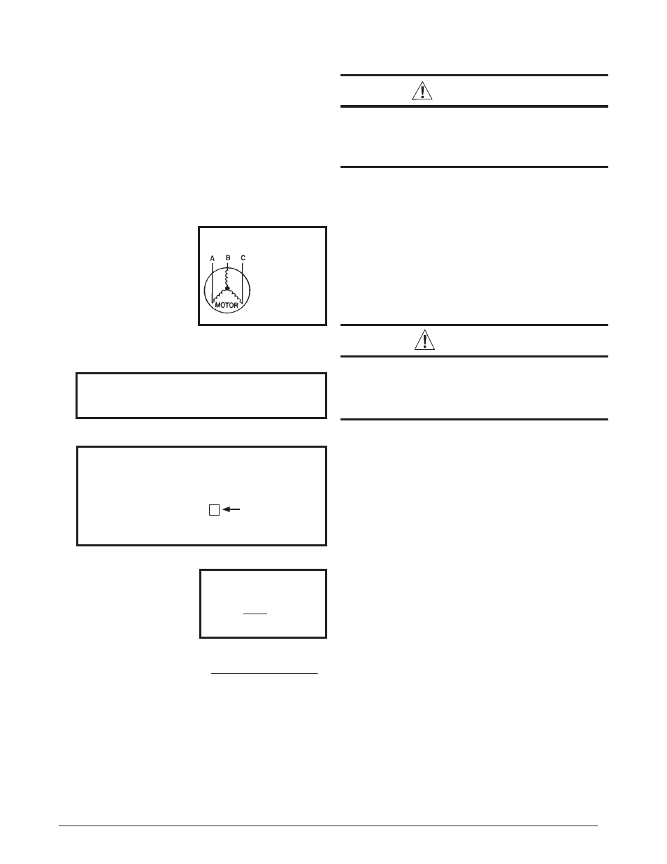
1. M e a s u r e t h e l i n e
voltages of your 3-phase
power supply where it
enters the building and
at a location that will
only be dedicated to the
unit installation. (at the
units circuit protection
or disconnect).
Unbalanced 3-Phase Supply Voltage
Voltage unbalance occurs when the voltages of all phases
of a 3-phase power supply are no longer equal. This
unbalance reduces motor effi ciency and performance.
Some underlying causes of voltage unbalance may include:
Lack of symmetry in transmission lines, large single-phase
loads, and unbalanced or overloaded transformers. A
motor should never be operated when a phase imbalance
in supply is greater than 2%.
Perform the following steps to determine the percentage
of voltage imbalance:
In this example, the measured line voltages were
451, 460, and 453. The average would be 454 volts
(451 + 460 + 453 = 1,364 / 3 = 454).
The amount of phase imbalance (1.32%) is satisfactory
since the amount is lower than the maximum allowable
2%. Please contact your local electric utility company if
your voltage imbalance is more than 2%.
Example:
From the values given in step 1, the BC voltage
(460V) is the greatest difference in value from
the average:
460 - 454 = 6
454 - 451 = 3
454 - 453 = 1
Highest Value
Grounding
WARNING:
The unit cabinet must have an uninterrupted or
unbroken electrical ground to minimize personal
injury if an electrical fault should occur. Do not
use gas piping as an electrical ground
!
This unit must be electrically grounded in accordance
with local codes or, in the absence of local codes, with
the National Electrical Code (ANSI/NFPA 70) or the CSA
C22.1 Electrical Code. Use the grounding lug provided in
the control box for grounding the unit.
Blower Speed
The blower speed is preset at the factory for operation at
the same speed for heating and cooling. These factory
settings are listed in Table 5 (page 21). For optimum
system performance and comfort, it may be necessary
to change the factory set speed.
CAUTION:
To avoid personal injury or property damage,
make sure the motor leads do not come into
contact with any uninsulated metal components
of the unit.
1. Shut off all electrical power to the unit and remove
the blower panel. Locate the orange and red wires
terminated to the blower motor. NOTE: The orange
wire controls cooling operation while the red wire
controls heating operation.
2. Verify the required speed from the airfl ow data found
in Table 5. Place appropriate wire on the correct motor
speed tap for the required airfl ow point.
Defrost Cycle Timer
The defrost cycle timer controls the time interval of the hot
gas defrost after the defrost sensor closes. It is located
in the lower left corner of the defrost control board on the
low voltage side of the control box. Three interval settings
are available: 30 minutes, 60 minutes, and 90 minutes.
Time setting selection is dependent on the climate where
the unit is being installed.
• Example 1: Dry climate of Southern Arizona - A 90
minute setting is recommended.
• Example 2: Moist climate of Seattle, Washington - A
30 minute setting is recommended.
To set the cycle timer, place the timing pin on the defrost
control board to the desired time interval post. NOTE: All
units are shipped from the factory with the default time
setting of 30 minutes.