Refrigerant line connections, Orifice removal & installation, Warning – Reznor B6BM Unit Installation Manual User Manual
Page 8: Caution
8
WARNING:
The coil in the air handler is factory shipped with
a nitrogen charge. Avoid direct face exposure
or contact with valve when gas is escaping.
Always ensure adequate ventilation is present
during the depressurization process. Address
any uncertainties before proceeding. Failure
to comply with this warning could result in
equipment damage, personal injury, or death.
Refrigerant Line Connections
• The installer should make every effort to ensure the
field installed refrigerant containing components of the
system have been installed in accordance with these
instructions and sound installation practices for reliable
system operation and longevity.
• The air handler coil does not contain a refrigerant charge.
Refer to the installation instructions supplied with the
outdoor unit for refrigerant charge information.
• Always refer to the installation instructions supplied with
the outdoor unit for piping requirements. The suction
and liquid lines must be sized in accordance with the
condensing unit specifications. See
for liquid and suction line locations.
• When connecting refrigerant linesets together, it is
recommended that dry nitrogen be flowing through the
joints during brazing. This will prevent internal oxidation
and scaling from occurring.
• Refrigerant tubing should be routed in a manner that
minimizes the length of tubing and the number of bends
in the tubing. It should be supported in a manner that
prevents it from vibrating or abrading during system
operation. Tubing should be kept clean of foreign debris
during installation.
• If precise forming of refrigerant lines is required, a copper
tubing bender is recommended. Avoid sharp bends and
contact of the refrigerant lines with metal surfaces.
NITROGEN
HEALTH
FLAMMABILITY
REACTIVITY
0 Minimal Hazard
1 Slight Hazard
1
0
0
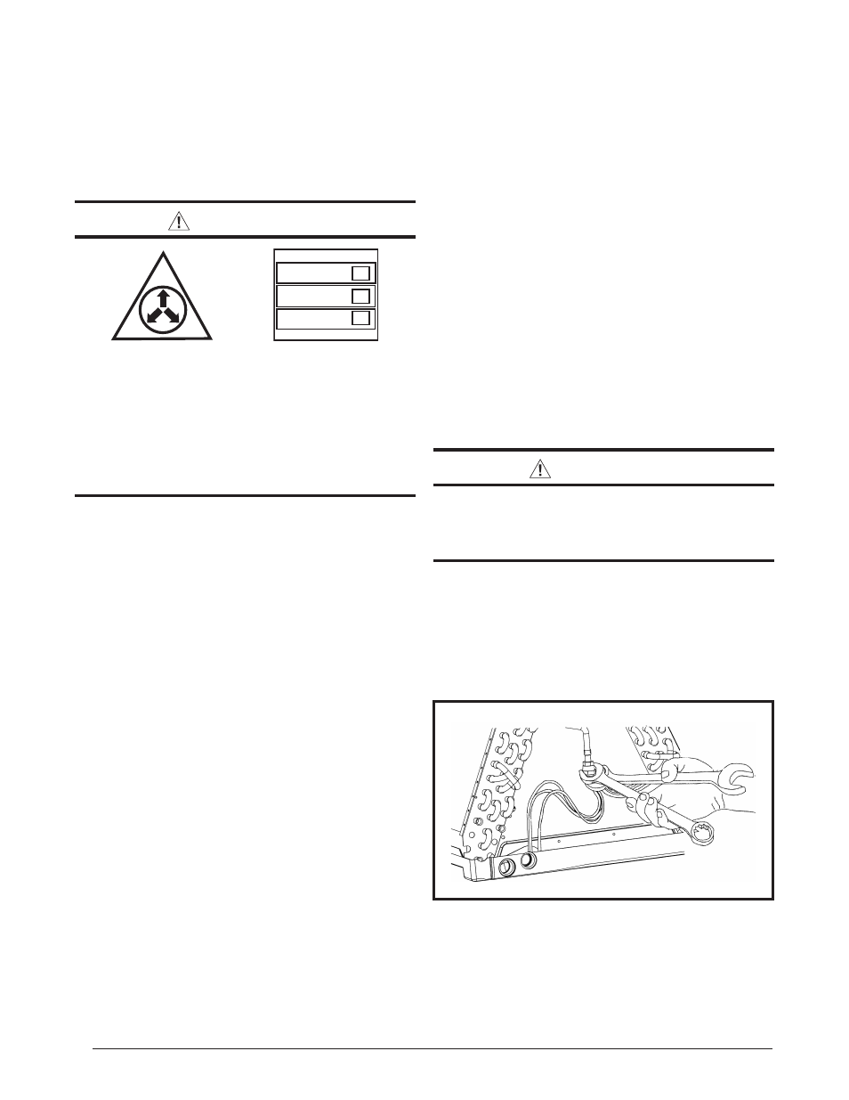
Figure 5. Loosening of Nut & Distributor Body
7. Insert the plug (from horizontal drain pan) into the open
and unused drain hole in the drain pan at the bottom
of the unit to block bypass air.
8. Remove the corresponding drain line knockout from
the coil access door to allow access to the horizontal
drain.
9. Replace the door and attach the drain line
• Refrigerant lines should be wrapped with pressure
sensitive neoprene or other suitable material where
they pass against sharp sheet metal edges.
• B6 Series air handlers are charged through service
valves on the end of the liquid tube for each circuit.
These must be removed before brazing the line sets.
Orifice Removal & Installation
The orifice installed in the air handler has been sized for
use with the most popularly matched outdoor units. The
orifice size as shipped from the factory is listed on the air
handler rating plate. Perform steps 1 - 9 to confirm that
the orifice size meets the requirements outlined in the
outdoor unit installation manual.
1. Remove the cap from the end of the liquid line.
2. Verify pressurization by depressing the Schrader valve
on the end of the liquid line. Listen for any escaping gas.
If there is no pressure, test the coil for leakage.
• If leakage is found, clearly mark the location of the leak
and return the coil to the distributor for processing.
• If no leaks are found, the coil may be installed.
3. Depress the valve to relieve all pressure from the coil.
4. Remove and discard the valve core.
CAUTION:
To prevent damage to the unit or internal
components, it is recommended that two
wrenches be used when loosening or tightening
nuts. Do not over tighten!
5. Using two wrenches, loosen the nut and distributor body
as shown in
. Turn the assembly nut counter-
clock-wise until the orifice body halves are seperated.
6. Insert a light-gauge wire hook between the distributor
body and the restrictor orifice while being careful not
to scratch either part. Carefully remove the restrictor
orifice from the distributor body. See