Reznor ACUB Option - Installation - ACU - Cased Cooling Coil User Manual
Page 7
Form I-CAUA-CC, P/N 166152R4, Page 7
Instructions for
Installing Burner
Condensate Drain
TABLE 6 - Burner
Condensate Drain
Components
Qty
P/N
Description
1
165955 6-ft length of 3/8" I.D. Tubing
1
165952 90° Nylon Fitting, 1/4" NPT x 3/8" tubing
1
110628 1/4" NPT Brass Nut
1
171527 1/4" Locknut, Hex, T& B 139
1
165953 Sealing Washer
2
20913 Nylon Wire Ties, T&B #TY-24M
1
87556 Snap Bushing, Heyco SB 625-8
3
1
4
2
Instructions:
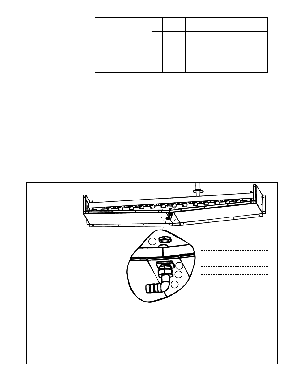
1) Assemble the brass nut, the sealing washer, and the 90° fitting.
2) Position the threaded fitting up through the hole so that the hose barb is toward the bushing that you
installed in the side of the cabinet. Attach using the silver-colored locknut.
3) Under the burner, push the tubing onto the hose barb, being sure that it is secure. Maintaining a
downward slope, extend the hose out through the bushing installed in the hole in the cabinet side.
4) Just after exiting the cabinet, create a trap in the line by making a loop in the hose. Secure the
loop with the wire ties.
5) Continue downward with the tubing, connecting it into the cooling coil drain pipe.
FIGURE 5 -
Burner
Condensate
Drain
Connection
Hex Locknut (silver)
— Burner Bottom Pan
Sealing Washer
Brass Nut
90° Nylon Fitting
1. Remove the burner compartment door.
2. Depending on date of manufacture, the burner box cover is in either two
sections (top left and top right extending over the front) or three sections
(top left, top right, and a separate front cover).
-- If the front of the burner cover is separate, remove the front section only.
-- If the front burner cover is not a separate piece, on the left side of the
burner box cover, disconnect the flame sensor wire and the flame rollout
switch wires. Disconnect the silicone tubing from the static tap. Remove the
top left cover.
3. Determine which side of the cabinet will be most convenient for the drain
line. Remove the hole plug on that side and replace with the snap bushing
from the package.
4. Locate the hole in the bottom center of the burner pan and remove the
plug. Follow the instructions in
FIGURE 5 to install the drain. Complete all
steps and re-assemble the heater.