4 heat section condensate drain, Cooling coil installation instructions (cont'd) – Reznor ACUB Option - Installation - ACU - Cased Cooling Coil User Manual
Page 6
Form I-CAUA-CC, Page 6
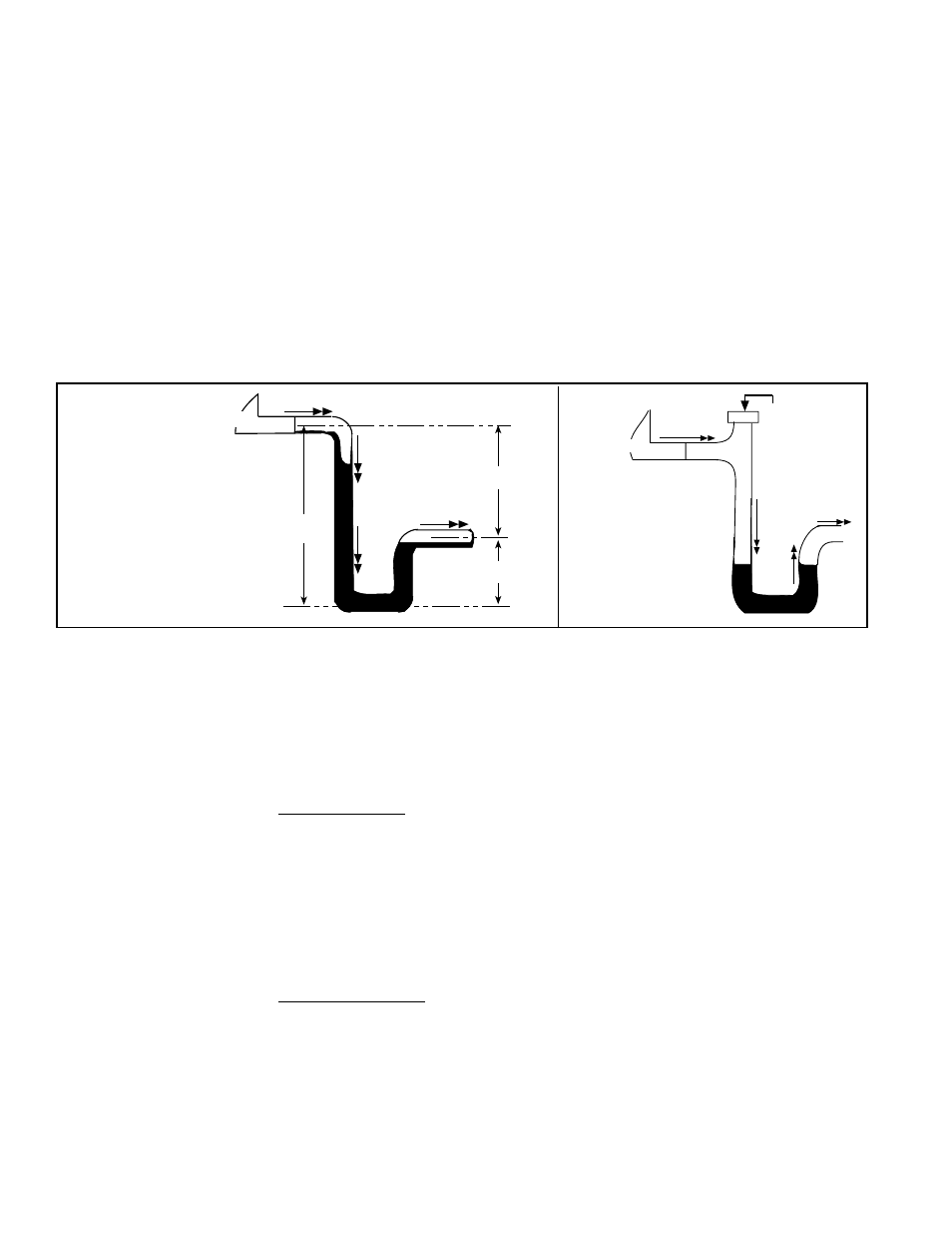
To prevent air
from entering
always close
the cleanout.
Water Flow
Unit
FIGURE 4B -
Drain
Trap with
Cleanout
B
A
A/2
C
L
C
L
C
L
Unit
Water Flow
Water Flow
A = 3" (76mm)
minimum
B = A + A/2
FIGURE 4A -
Condensate
Drain Trap
Dimensions
Improper trap design accounts for some condensate drainage system failures,
but incorrect use and maintenance of condensate drain traps can also cause
problems. The combination of airborne particles and moisture in the air handler
can result in algae formation in the drain pan and traps. The traps must be
cleaned regularly to avoid blockage that can slow or stop water flow, resulting
in backup into the system.
If drains have a cleanout opening (
FIGURE 4B), be sure to close the opening
after cleaning.
Condensate Drain
Use
4. Cooling Coil
Installation
Instructions
(cont'd)
4.4 Heat Section
Condensate
Drain
When a cooling coil is installed on a Model CAUA heater, a heat section con-
densate drain line must be installed.
The parts to install the drain line are packaged and shipped with all Model
CAUA heaters.
Seasonal Usage - At the beginning of the cooling season, inspect and clean
the entire cooling coil cabinet including the condensate drain pan. Thoroughly
clean dirt, algae, grease, and other contaminates. Inspect condensate drain
pans, traps, and piping; fill traps with water to ensure proper operation. During
a wintertime shutdown of the cooling system it may be desirable to disconnect
and remove all water from the traps and drains to prevent freeze damage. If
local building codes permit, traps may be filled with an antifreeze solution. Or,
piping may be designed with freeze plugs or other freeze protection methods
(such as a heat tape).
Year Round Usage - Climates or applications with cooling requirements year
round require more frequent inspections of the cooling coil cabinet and conden-
sate drains. Depending on climate, freeze protection of traps may be required
during non-cooling hours.
Condensate Drain Trap
The design of the drain trap is important. If dimension "B" in
FIGURE 4A is
not tall enough, the water seal will not hold, and air will be drawn through the
drain pipe into the system. If the outlet leg of the trap is too tall, water will back
up into the drain pan. As condensate forms during normal operation, the water
level in the trap rises until there is a constant outflow.
FIGURE 4A illustrates
the appropriate dimensions.
4.3 Drain Line
The cased coil has a 3/4" FPT drain connection; see location in
FIGURE 1.
page 2. Install a trap (see below) and pitch the drain line downward at least 1/2"
(13mm) for every 10 feet (3M) of horizontal run. Drain lines must not interfere
with access panels. An obstruction in the drain or a poorly designed drain can
cause an over flow. Overflow could result in unit or building damage.
Connect the heat section condensate tubing (see Paragraph 4.4) into the cool-
ing coil drain line and continue into a sanitary drain system.
Condensate Drain
Trap