Uncrating and preparation, Dimensions, Figure 1 - dimensions of cased cooling coil – Reznor ACUB Option - Installation - ACU - Cased Cooling Coil User Manual
Page 2
Form I-CAUA-CC, Page 2
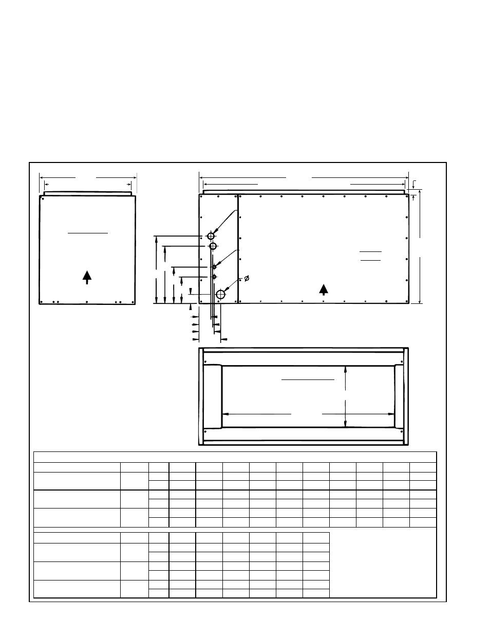
FIGURE 1 -
Dimensions of
Cased Cooling
Coil
3. Dimensions
A
G
F
H
J
K
Q
P
N
M
3/4 FPT Drain
Airflow
1(25)
B
D (Outlet Duct Flange)
Hole Locations: Suction Lines FxQ and GxP;
Liquid Lines HxN and JxN; and Drain KxM
Front
View
Suction Line Connections -
Circuit A, Bottom; Circuit B, Top
Liquid Line Connections -
Circuit A, Bottom; Circuit B, Top
R
S
Drain Pan Opening
R x S
Bottom View
E
(Outlet Duct Flange)
Side View
Airflow
C
TABLE 2 - Dimensions of Cased Cooling Coil
Option C for Model CAUA
Model
A
B
C
D
E
F
G
H
J
K
Option C060, C072, C090
for CAUA 150 or 200
All
ACUA
inches
27
38
23
36
21
16-1/2
--
8-1/2
--
2-1/8
mm
686
965
584
914
533
419
--
217
--
54
Option C090, C120, C150
for CAUA 250 or 300
All
ACUB
inches
27
50
23
48
21
16
13-5/8
8-5/8
6-1/4
2-1/8
mm
686
1270
584
1219
533
406
346
219
159
54
Option C120, C150, C180
for CAUA 350 or 400
All
ACUC
inches
32-5/8
50
36
48
34
20-1/2 17-1/4
9-1/4
7-3/4
2-1/8
mm
829
1270
914
1219
864
521
438
235
197
54
Option C for Model CAUA
Model
M
N
P
Q
U
V
Hole Locations:
Suction Lines, Circuit B - FxQ
and Circuit A - GxP
Liquid Lines, Circuit B - HxN and
Circuit A, JxN
Drain, KxM
NOTE: See tubing sizes in chart
on page 4.
Option C060, C072, C090
for CAUA 150 or 200
All
ACUA
inches
6
4
--
3-1/2
14-1/2
27
mm
152
102
--
89
368
686
Option C090, C120, C150
for CAUA 250 or 300
All
ACUB
inches
5-1/8
3-5/8
3-1/4
2-3/4
14-1/2 41-1/4
mm
130
92
83
70
368
1048
Option C120, C150, C180
for CAUA 350 or 400
All
ACUC
inches
4-1/4
5-3/4
4-1/4
3
27-1/2 39-7/8
mm
108
146
108
76
699
1013
2. Uncrating and
Preparation
Uncrate and inspect the cooling coil. If damage has been incurred during ship-
ment, document the damage with the transporting agency and contact an
authorized Reznor Distributor. If you are an authorized Distributor, follow the
freight policy procedures as published by Reznor for Reznor products.
Check the rating plate for the specifications and electrical characteristics to
be sure that they are compatible with the installation. Locate the thermostatic
expansion valve(s) that are shipped loose. Size 060 will have either one or two
valves. Size 072 will have one valve. Sizes 090-180 will have two valves. If a
reducer is required to connect the thermostatic expansion valve to the distribu-
tor, the required reducers are shipped with the valves. Refer to the appropriate
chart on page 4 and verify that the valves are correct for the installation.