Cooling coil installation instructions (cont'd), 2 thermostatic expansion valves (cont'd), Never place bulb in a trap or downstream of a trap – Reznor ACUB Option - Installation - ACU - Cased Cooling Coil User Manual
Page 4: Position bulb on the tubing as shown in figure 3a, Bulb must have 100% contact with tubing, Secure the bulb tightly
Form I-CAUA-CC, Page 4
4. Cooling Coil Installation Instructions (cont'd)
4.2 Thermostatic Expansion Valves (cont'd)
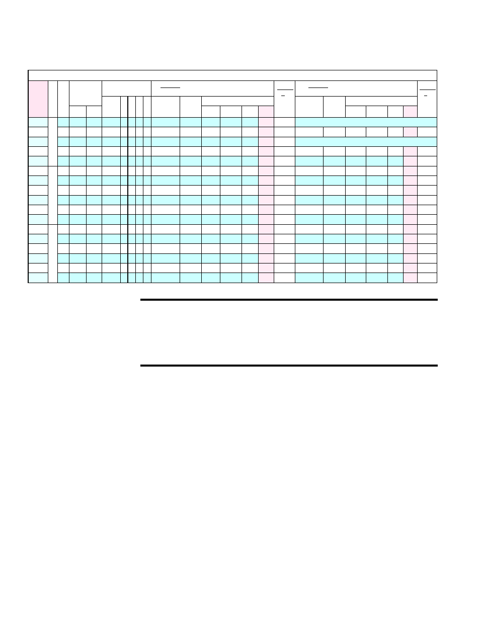
TABLE 4 - Thermostatic Expansion Valves (TEV) and Tubing Sizes
Thermostatic Expansion Valve Kit (shipped with the Cased Cooling Coil) and Tubing Sizes by Model, Size, and Circuit
TEV Kit
P/N for
R-410A
Model
Size
Circuit
Evaporator Coil
Circuit A (Bottom Liquid Line Connection; see
FIGURE 1) - *TEV inlet is liquid line tubing size.
Circuit
A -
Suction
Line
Tubing
Circuit B (Top Liquid Line Connection; see
FIGURE 1) - *TEV inlet is liquid line tubing size.
Circuit
B -
Suction
Line
Tubing
Reznor
P/N
Row
FH
FL
FPI
Distributor
(on coil)
Connection
Field-
Installed
Reducer
Field-Installed TEV
Distributor
(on coil)
Connection
Field-
Installed
Reducer
Field-Installed TEV
Desc. Code
P/N
Mfr
Outlet *Inlet
P/N
Mfr.
Outlet *Inlet
258856
A
C
U
A
060 Single AUD1
257328 2 20 28 10
5/8
216428 234052 BBIZE-5
7/8
5/8
7/8
258858
060 1/3-2/3 AUD3
258846 2 20 28 10
5/8
None 220552 BBIZE-2
5/8
1/2
7/8
5/8
None
220553 BBIZE-3 5/8
5/8
7/8
258857
072 Single AUD1
257329 2 20 28 12
7/8
None 220555 BBIZE-6
7/8
5/8
7/8
258860
090 50/50 AUD2
257538 3 24 28 10
5/8
216428 220554 BBIZE-4 7/8
5/8
7/8
5/8
216428 220554 BBIZE-4 7/8
5/8
7/8
258861
090 1/3-2/3 AUD3
257330 3 24 28 10
5/8
None 220553 BBIZE-3
5/8
5/8
7/8
5/8
216428 234052 BBIZE-5 7/8
5/8
7/8
258860
A
C
U
B
090 50/50 AUD2
257539 2 24 42 12
5/8
216428 220554 BBIZE-4
7/8
5/8
7/8
5/8
216428 220554 BBIZE-4 7/8
5/8
7/8
258861
090 1/3-2/3 AUD3
257331 2 24 42 12
5/8
None 220553 BBIZE-3
5/8
5/8
7/8
5/8
216428 234052 BBIZE-5 7/8
5/8
7/8
258862
120 50/50 AUD2
257540 3 20 42 10
5/8
216428 234052 BBIZE-5
7/8
5/8
7/8
5/8
216428 234052 BBIZE-5 7/8
5/8
7/8
258863
120 1/3-2/3 AUD3
257332 3 20 42 10
5/8
None 220553 BBIZE-3
5/8
5/8
7/8
7/8
None
220555 BBIZE-6 7/8
5/8
7/8
258864
150 50/50 AUD2
257541 3 24 42 12
7/8
None 220555 BBIZE-6
7/8
5/8
7/8
7/8
None
220555 BBIZE-6 7/8
5/8
7/8
258865
150 1/3-2/3 AUD3
257333 3 24 42 12
5/8
216428 220554 BBIZE-4
7/8
5/8
1-3/8
7/8
None
220557 BBIZE-8 7/8
5/8
7/8
258862
A
C
U
C
120 50/50 AUD2
257542 2 30 41 12
5/8
216428 234052 BBIZE-5
7/8
5/8
1-3/8
5/8
216428 234052 BBIZE-5 7/8
5/8
1-3/8
258863
120 1/3-2/3 AUD3
257334 2 30 41 12
5/8
None 220553 BBIZE-3
5/8
5/8
1-3/8
7/8
None
220555 BBIZE-6 7/8
5/8
7/8
258864
150 50/50 AUD2
257543 3 27 41 10
7/8
None 220555 BBIZE-6
7/8
5/8
1-3/8
7/8
None
220555 BBIZE-6 7/8
5/8
1-3/8
258866
150 1/3-2/3 AUD3
257335 3 27 41 10
5/8
216428 220554 BBIZE-4
7/8
5/8
1-3/8
1-1/8
216432 220557 BBIZE-8 7/8
5/8
7/8
258867
180 50/50 AUD2
257544 3 30 41 10
1-1/8
216432 220557 BBIZE-8
7/8
5/8
1-3/8
1-1/8
216432 220557 BBIZE-8 7/8
5/8
1-3/8
258868
180 1/3-2/3 AUD3
257336 3 30 41 10
5/8
216428 234052 BBIZE-5
7/8
5/8
1-3/8
1-1/8
216432 220557 BBIZE-8 7/8
5/8
7/8
CAUTION: The thermostatic expansion valve must be for
R-410A refrigerant and must be sized to match the circuit.
Failure to correctly select and install thermostatic expansion
valve(s) will prevent the system from operating properly and
will void the manufacturer’s warranty.
After the refrigerant lines are installed and before charging, extend the ther-
mostatic expansion valve bulb from the valve to the suction line. If there are
two circuits, be sure to match the liquid line with the corresponding suction
line. Comply with the illustration in
FIGURE 3A and the valve manufacturer’s
instructions on bulb placement. General recommendations are listed below.
•
Place bulb on suction line as close to the evaporator coil outlet as possible.
•
Place the bulb on a straight horizontal section of suction line (if bulb must
be vertical, line must be descending).
•
Never place bulb in a trap or downstream of a trap.
•
Position bulb on the tubing as shown in
FIGURE 3A.
•
Bulb must have 100% contact with tubing.
•
Secure the bulb tightly.
•
Cover bulb with waterproof insulation.
In addition, an external equalizer line must be installed from the stem on the
valve to a location on the suction line that is downstream of the bulb. Follow the
instructions in
FIGURE 3B to install the field-provided tubing.
NOTE: For replacement
information, including
TEV's for R22 refrigerant,
see Form P-CAUA at
www.RezSpec.com..