3 drain line – Reznor ACUB Option - Installation - ACU - Cased Cooling Coil User Manual
Page 5
Form I-CAUA-CC, P/N 166152R4, Page 5
Bulb at
3 o’clock
Bulb at
4 o’clock
Bulb at
8 o’clock
Bulb at
9 o’clock
12
3
6
9
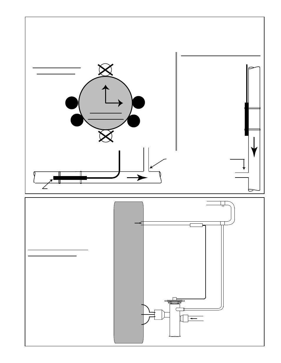
Position bulb flat against the surface of the suction line tubing. Secure bulb
tightly and insulate.
Suction Line
Cross Section
Suction Line
Thermostatic Expansion Valve Bulb
Suction Line
Thermostatic
Expansion
Valve Bulb
(Capillary tube should
be out the top.)
Horizontal Section
of Suction Line
(preferred location)
Vertical Section of Suction Line
(descending flow only)
Capillary
tubing
from TEV
Capillary tubing from TEV
Connect field-supplied
equalizer tubing from the TEV
(FIGURE 3B) into the
suction line a short
distance downstream
of the bulb.
FIGURE 3A - Suction Line showing Orientation and Location of the Thermostatic
Expansion Valve Bulb and the Equalizer Tubing (applies to each circuit)
External equalizer
line requires field-
supplied tubing
from the 1/4” ODF
fitting on the valve
and connected
into the suction
line preferably at
location “X” down-
stream of the
TEV bulb. If “X” is
not possible,
location “Y” is
acceptable as long
as pressure is
essentially the
same as at “X”.
Thermostatic
Expansion
Valve (TEV)
Evaporator Coil in Model
ACU or Option C
Cased Cooling Coil
TEV
Bulb
Suction Line
X
Y
Thermostatic Expansion
Valve Equalizer Line - To
ensure that the correct pressure
is signaled to the valve, an
external equalizer line must
be connected into the
suction
line downstream of the
thermostatic expansion valve
bulb. (See location indicated in
FIGURES 3A and 3B.)
Connect the other end of the
equalizer tubing to the 1/4"
ODF stem on the thermostatic
expansion valve as shown in
FIGURE 3B.
FIGURE 3B - Thermostatic
Expansion Valve with
External Equalizer Line
Fitting (required for each
circuit)