24v thermostat, Other burners burner 1, 110v thermostat – Reznor VPS Unit Installation Manual User Manual
Page 8: Other burners
8
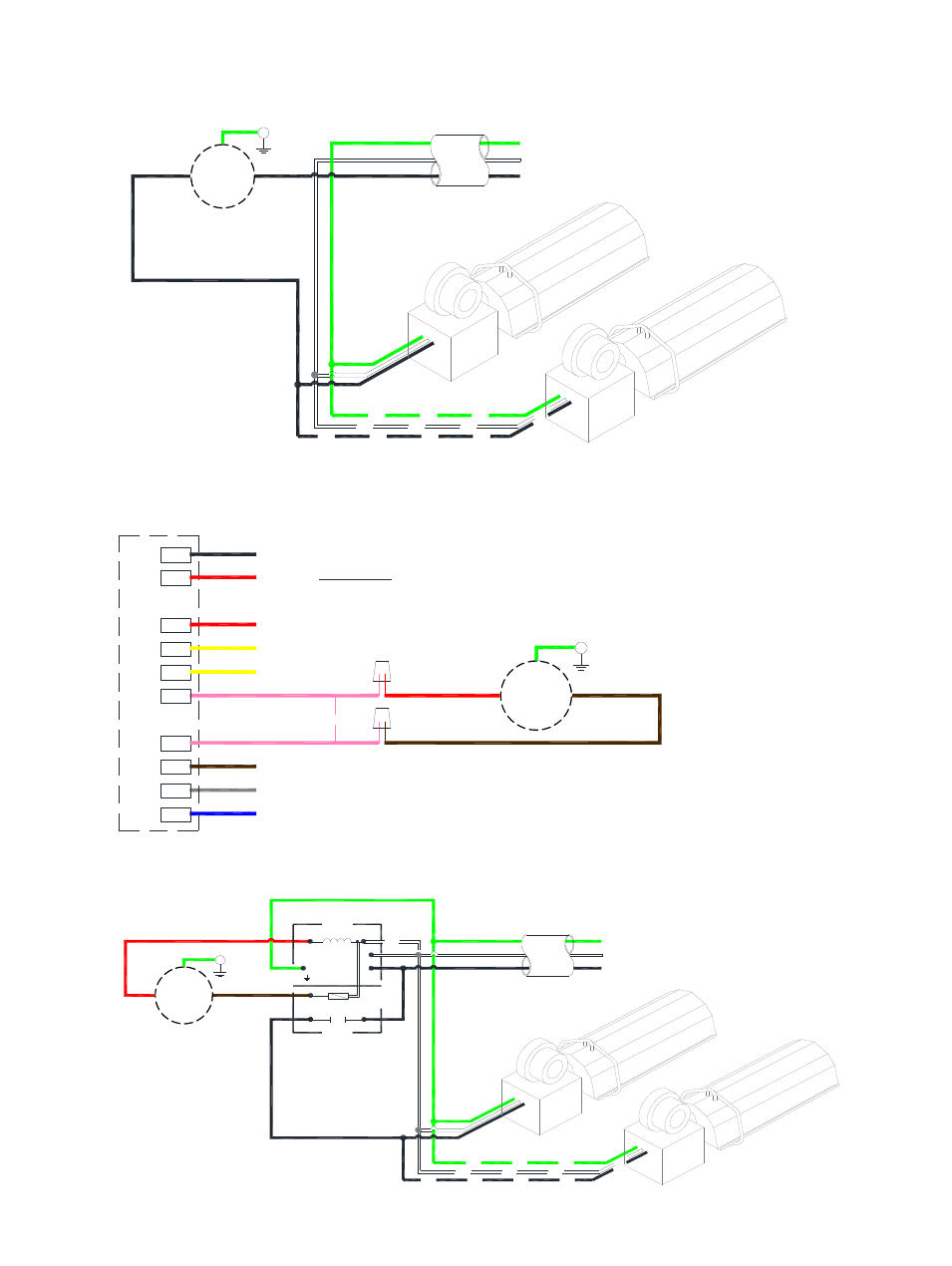
Figure 5a. Single and Multiple Heater Installations 120V Control
Supply circuit
120V 60Hz 1 Ph
L2
L1 (HOT)
GND
other burners
Burner 1
T
110V Thermostat
Figure 5b. Single Heater Installations 24V Control
L1
Gas
C
ontrol
MV
X
C
COM
W1
PS0
PS1
IND
R
BK
R
Y
K
BR
GR
BL
K
Y
R
T
24V Thermostat
R
W1
C
X
METHOD:-
Cut and strip pink cables linking terminals W1 and R
Attach thermostat wires using suitable wire nuts.
KEY:
BL - BLUE
BK - BLACK
BR - BROWN
GR - GREY
K - PINK
R - RED
Y - YELLOW
Figure 5c. Multiple Heater Installations 24V Control
120V Thermostat
Supply circuit
120V 60Hz 1 Ph
S-0700
C
40VA
Trans
Relay
L1
G
R
L2
L2
L1 (HOT)
GND
T
24V Thermostat
other burners
Burner 1
R
W1
C
Fan center relay
(Suppled by others)
30
KEY:
G-GREEN
W-WHITE
BK-BLACK
Other burners
BK
G
W
W
BK
G
BK
KEY:
G - GREEN
W - WHITE
BK - BLACK
R - RED
G
R
BK
W
W
BK
BK
Other burners
T
T
T
- UDAP Unit Installation Manual (40 pages)
- UDBP Unit Installation Manual (44 pages)
- UEAS Unit Installation Manual (44 pages)
- VPT Unit Installation Manual (40 pages)
- VCS Unit Installation Manual (48 pages)
- CAUA Unit Installation Manual (44 pages)
- EEDU Unit Installation Manual (32 pages)
- LDAP Unit Installation Manual (44 pages)
- MASA Unit Installation Manual (40 pages)
- RDF Unit Installation Manual (28 pages)
- RPB Unit Installation Manual (40 pages)
- SC Duct Furnace Unit Installation Manual (40 pages)
- SSCBL Unit Installation Manual (60 pages)
- X Unit Installation Manual (32 pages)
- ZQYRA Unit Installation Manual (72 pages)
- ADF Unit Installation Manual (28 pages)
- F Unit Installation Manual (40 pages)
- PDH (Indoor PreevA) Unit Installation Manual (72 pages)
- MAPSIII Unit Installation Manual (76 pages)
- RDH (Outdoor PreevA) Unit Installation Manual (68 pages)
- RP (Outdoor Duct Furnaces) Unit Installation Manual (32 pages)
- YDHA Unit Installation Manual (76 pages)
- OH Unit Installation Manual (28 pages)
- RBL (Cabinet Blower) Unit Installation Manual (12 pages)
- REC (Evaporative Cooling) Unit Installation Manual (12 pages)
- RIHN Unit Installation Manual (20 pages)
- UDAP Option - Installation - Power Venting (12 pages)
- UDAS Option - Installation - Separated Combustion Venting (16 pages)
- WS Unit Installation Manual (15 pages)
- EBHB Option - Installation - Thermostat Kit (2 pages)
- EFMA Unit Installation Manual (27 pages)
- EWHB Unit Installation Manual (9 pages)
- EXUB Unit Installation Manual (16 pages)
- XAWS Unit Installation Manual (12 pages)
- XAWU Unit Installation Manual (12 pages)
- XBWU Unit Installation Manual (12 pages)
- MAPS III Option - Installation - Energy Recovery Module Installation (12 pages)
- UDAP in sizes 30 through 125 Option - Installation - Ceiling Suspension Kit (2 pages)
- UEAS Option - Installation - Downturn Nozzles - V3 (4 pages)
- UDBP Option - Installation - Polytube Adapter Instructions (4 pages)
- UDBS Option - Installation - Vertical Louvers - V3 Series (2 pages)
- B Option - Installation - Blower/Filter Cabinet (4 pages)
- PDH with 1-stage gas control or 2-stage gas control Gas Conversion Kit Instructions (8 pages)
- VP series infrared heaters High altitude conversion instructions (12 pages)