Reznor VPS Unit Installation Manual User Manual
Page 17
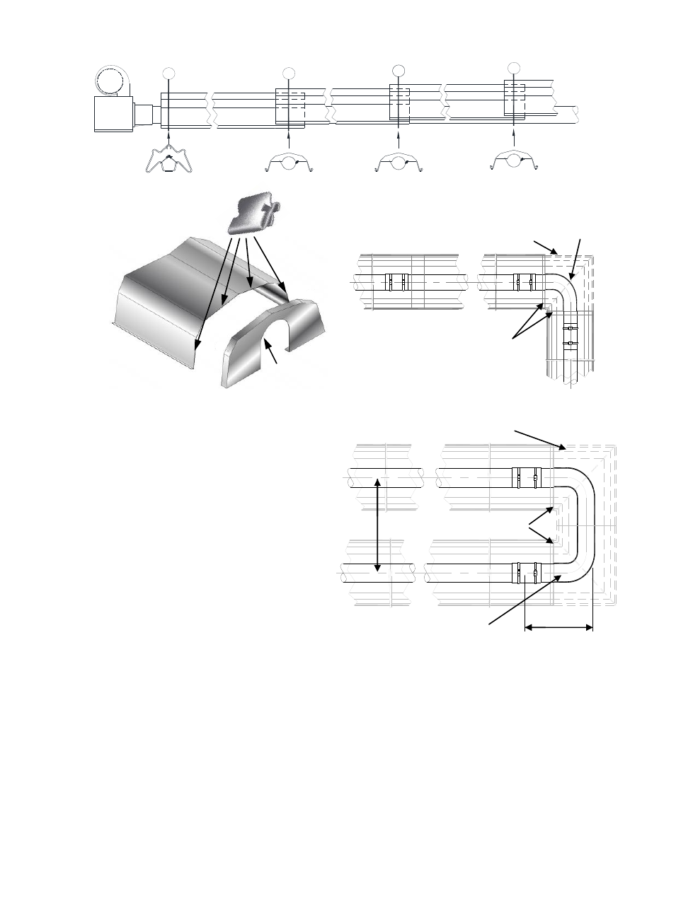
Typical usage of optional bend kits:
2.2.9 Detailed Assembly Drawings
The following pages show the technical
dimensional details of the range of heaters.
Please note the heater type, length and
reference number from the delivery/advice note
before identifying the correct model drawing.
2.2.6 End Caps (optional)
Position an end cap beneath the reflector
profile (where required) with the end cap
flanges facing inwards. Fasten to reflector
using the four ’Z’ clips.
2.2.7 Bend(s) (where fitted)
The heater can be installed with 1 or 2 90°
bends or a 180° U bend.
Slide the bend into the open end of the
coupler ensuring that the screw stop has butted
up to the tube ends. Refer to 2.2.4 for
fastening.
2.2.8 Burner/Fan Assembly.
Slide the burner assembly onto the open tube
end, ensuring it is fully engaged. Secure with
set screws.
For the purpose of unvented applications, a 4”
90° elbow should be used on the terminating
end of the radiant tube sections. This elbow
should be turned with the outlet facing either
side.
Connect Gas and Electrical supplies as
described in sections 1.4 and 1.5.
17
90° Bend
End Caps
Corner reflector
End Caps
1
6
” c
rs
15”
U Bend
Corner reflectors (optional)
ASSEMBLY
H
REFLECTORS
F
S
F
BURNER
End Cap
Corner reflectors kit
90° Elbow