Carrier OMNIZONE 50XCA06-24 User Manual
Page 29
29
TB3
3
LOGIC
1
2
CLO1
HPS1
FRZ1
LPS1
TB2
A
B
C1
523
BLU
524
BLU
528
BRN
527
BLU
522
BLU
529
BRN
R
C
G
A
B
IFC
Y1
529
BRN
526
BLK
525
BLK
96
95
IFR
Y2
1
3
CR1
509
BRN
511
BRN
519
BRN
531
BRN
530
PNK
520
BLU
4
2
CR1
510
BLK
501
RED
501
RED
561
RED
509
BRN
510
BLK
520
BLU
530
PNK
3
LOGIC
1
2
CLO2
HPS2
FRZ2
LPS2
A
B
C2
534
PNK
535
PNK
539
BRN
538
PNK
533
PNK
540
BRN
540
BRN
537
BLK
536
BLK
532
PNK
A
B
OFC
96
95
OFR
521
BLU
TO LINE
VOLTAGE
{
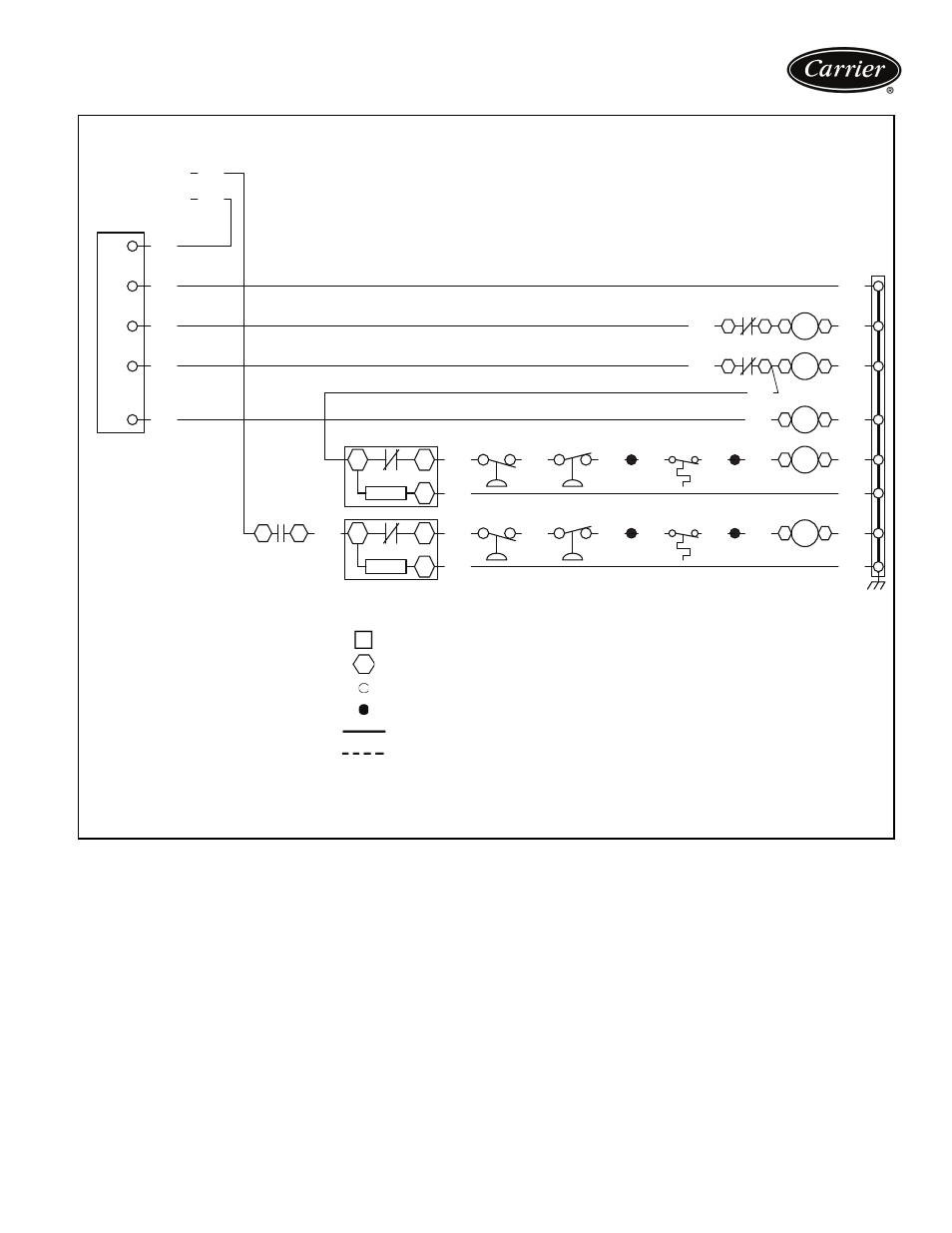
LOW VOLTAGE DIAGRAM — 50XCA012-024, 208/230-3-60 UNITS SHOWN
NOTES:
1. Fan motors are inherently thermally protected.
2. Three-phase motors are protected under primary
single phase conditions.
3. Use conductors suitable for at least 194 F (90 C)
when replacing factory wiring.
4. Use copper conductors only.
5. Wiring for field power supply must be rated at 165 F
(75 C) minimum.
LEGEND
C
—
Compressor Contactor
CH
—
Crankcase Heater
CLO
—
Compressor Lockout
COMP —
Compressor
FRZ
—
Freeze Protection
HPS
—
High Pressure Switch
IFC
—
Indoor-Fan Contactor
IFR
—
Indoor-Fan Relay
OFC
—
Outdoor-Fan Contactor
OFR
—
Outdoor-Fan Relay
TB
—
Terminal Block
Terminal Block Connection
Marked Terminal
Unmarked Terminal
Splice
Factory Wiring
Field Power Wiring
a50-8505