Typical wiring schematic, Typical wiring schematic ,29, L2 l3 l1 gnd – Carrier OMNIZONE 50XCA06-24 User Manual
Page 28
28
IFM
COMP1
121/BLK
123/BLU
122/YEL
118/BLK
120/BLU
119/YEL
C1
125/BLK
126/BLK
CH1
TB1
CLO1-Loop
103/BLK
104/YEL
105/BLU
106/BLK
107/YEL
108/BLU
109/GRN
111/BLK
112/YEL
113/BLU
2
1
3
T2
L2
T1
L1
T3
L3
150/BLK
151/YEL
501/RED
500/BRN
IFC/IFR
DISC1
L2
L3
L1
GND
100/BLK
101/BLK
102/BLK
T3
L3
T2
L2
T1
L1
114BLK
115/YEL
116/BLU
117/GRN
OFM
2
1
3
GND
124/GRN
2
1
3
COMP2
130/BLK
132/BLU
131/YEL
127/BLK
129/BLU
128/YEL
C2
134/BLK
135/BLK
CH2
CLO2-Loop
T2
L2
T1
L1
T3
L3
133/GRN
2
1
3
152/BLK
153/YEL
561/RED
560/BRN
TB3
OFC/OFR
T3
L3
T2
L2
T1
L1
208/230V
3
60 Hz
TRAN1
2
4
V
Cl
as
s
2
208V
240V
COM
TRAN2
2
4
V
Cl
as
s
2
208V
240V
COM
~
~
TO LOW
VOLTAGE
DIAGRAM
TO LOW
VOLTAGE
DIAGRAM
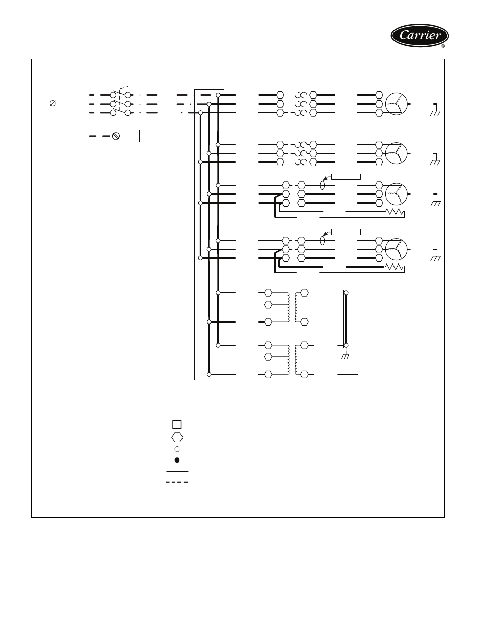
LEGEND
C
—
Compressor Contactor
CH
—
Crankcase Heater
CLO
—
Compressor Lockout
COMP —
Compressor
DISC
—
Disconnect
GND
—
Ground
IFC
—
Indoor-Fan Contactor
IFM
—
Indoor-Fan Motor
IFR
—
Indoor-Fan Relay
OFC
—
Outdoor-Fan Contactor
OFM
—
Outdoor-Fan Motor
OFR
—
Outdoor-Fan Relay
TB
— Terminal Block
TRAN — Transformer
Terminal Block Connection
Marked Terminal
Unmarked Terminal
Splice
Factory Wiring
Field Power Wiring
NOTES:
1. Fan motors are inherently thermally protected.
2. Three-phase motors are protected under primary
single phase conditions.
3. Use conductors suitable for at least 194 F (90 C)
when replacing factory wiring.
4. Use copper conductors only.
5. Wiring for field power supply must be rated at 165 F
(75 C) minimum.
LINE VOLTAGE DIAGRAM — 50XCA012-024, 208/230-3-60 UNITS SHOWN
a50-8504
Typical wiring schematic