Carrier 50JS User Manual
Page 20
To change the speed of the blower motor (BM), remove the fan
motor speed leg lead from the blower relay (BR). This wire is
attached to IGC terminal BM for single-phase and 3-phase units.
To change the speed, remove and replace with lead for desired
blower motor speed. Insulate the removed lead to avoid contact
with chassis parts.
For 460-v GE Motors—The motor leads are color coded as
follows:
3-SPEED
Black = high
Violet = jumper
Orange = medium
Red = low
To change the speed of the blower motor (BM), remove fan motor
speed lead from the blower relay (BR) and replace with the lead
for the desired blower motor speed. The motor speed lead is
attached to terminal BM. For low and medium speeds black must
be connected to the jumper wire. Insulate removed lead end to
avoid contact with chassis parts. To select high speed on 460-v GE
motors, separate the black female quick connect (QC) from the
jumper lead male quick connect (QC) and connect the black lead
to the BR. Insulate the jumper to avoid contact with any chassis
parts.
MAINTENANCE
To ensure continuing high performance, and to minimize the
possibility of premature equipment failure, periodic maintenance
must be performed on this equipment. This heat pump unit should
be inspected at least once each year by a qualified service person.
To troubleshoot unit, refer to Table 5.
NOTE TO EQUIPMENT OWNER: Consult your local dealer
about the availability of a maintenance contract.
The ability to properly perform maintenance on this equip-
ment requires certain expertise, mechanical skills, tools and
equipment. If you do not possess these, do not attempt to
perform any maintenance on this equipment, other than those
procedures recommended in the User’s Manual. FAILURE
TO HEED THIS WARNING COULD RESULT IN SERI-
OUS INJURY OR DEATH AND POSSIBLE DAMAGE TO
THIS EQUIPMENT.
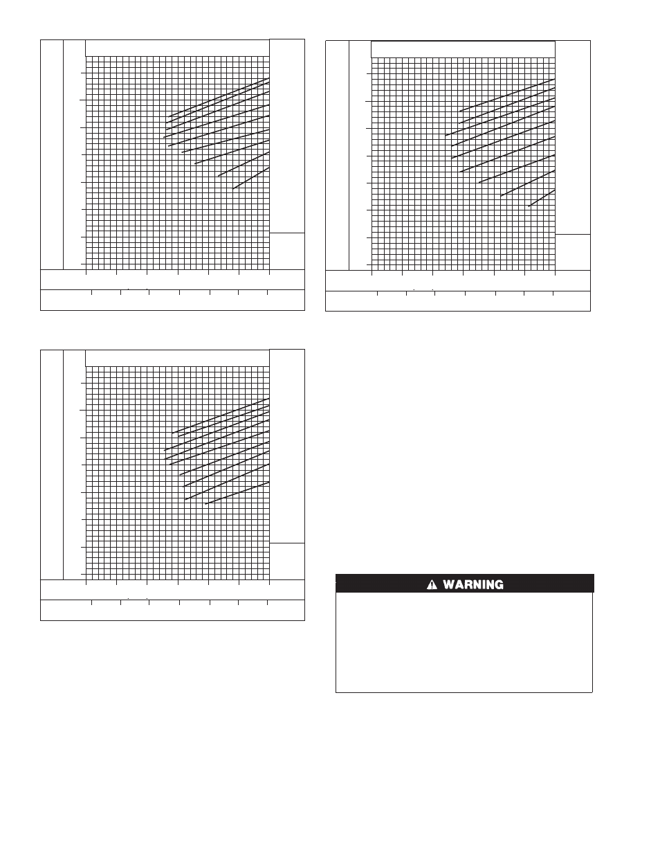
Fig. 27—Cooling Charging Chart, 50JS 042 Units
C00030
SUCTION LINE PRESSURE (KILOP
ASCALS)
SUCTION LINE PRESSURE (PSIG)
-7
-1
4
10
16
21
27
SUCTION LINE TEMPERATURE (
°
F)
SUCTION LINE TEMPERATURE (
°
C)
689
620
551
483
414
345
276
207
100
90
80
70
60
50
40
30
(042) 60HZ CHARGING CHART
20.0
30.0
40.0
50.0
60.0
70.0
80.0
OUTDOOR TEMP
°
F
°
C
115
46
125
52
45
7
55
13
65
18
75
24
95
35
105
41
85
29
50JS500091
Fig. 28—Cooling Charging Chart, 50JS 048 Units
C00031
SUCTION LINE PRESSURE (KILOP
ASCALS)
SUCTION LINE PRESSURE (PSIG)
-7
-1
4
10
16
21
27
SUCTION LINE TEMPERATURE (
°
F)
SUCTION LINE TEMPERATURE (
°
C)
689
620
551
483
414
345
276
207
100
90
80
70
60
50
40
30
(048) 60HZ CHARGING CHART
20.0
30.0
40.0
50.0
60.0
70.0
80.0
OUTDOOR TEMP
°
F
°
C
115
46
125
52
45
7
55
13
65
18
75
24
95
35
105
41
85
29
50JS500092
Fig. 29—Cooling Charging Chart, 50JS 060 Units
C00032
SUCTION LINE PRESSURE (KILOP
ASCALS)
SUCTION LINE PRESSURE (PSIG)
-7
-1
4
10
16
21
27
SUCTION LINE TEMPERATURE (
°
F)
SUCTION LINE TEMPERATURE (
°
C)
689
620
551
483
414
345
276
207
100
90
80
70
60
50
40
30
(060) 60HZ CHARGING CHART
20.0
30.0
40.0
50.0
60.0
70.0
80.0
OUTDOOR TEMP
°
F
°
C
115
46
125
52
45
7
55
13
65
18
75
24
95
35
105
41
85
29
50JS500093
20