Fig. 15—electrical data legend, Fig. 16—control connections, Fig. 17—line power connections – Carrier 50JS User Manual
Page 14: Fig. 18—control wiring plate
be in a conduit until they enter the duct panel; conduit termination
at the duct panel must be watertight. Run the high-voltage leads
through the power entry knockout on the power entry side panel
(See Fig. 2 and 3 for location and size). When the leads are inside
the unit, run leads up the high-voltage raceway to the line wiring
splice box (See Fig. 12 through 14). For single-phase units,
connect leads to the black and yellow wires; for 3-phase units,
connect the leads to the black, yellow, and blue wires (See Fig.
17).
CONNECTING GROUND LEAD TO GROUND LUG — Refer
to Fig. 17. Connect the ground lead to the chassis using the ground
lug in the wiring splice box.
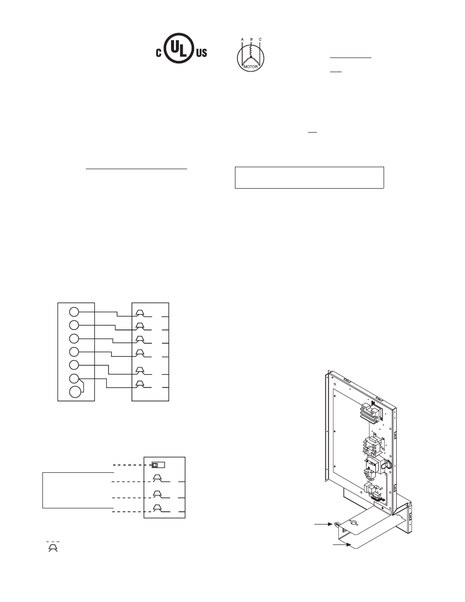
ROUTING CONTROL POWER WIRES — (24 V) — Form a
drip-loop with the thermostat leads before routing them into the
unit. Route the thermostat leads through grommeted, low-voltage
hole provided in unit into unit control power splice box (See Fig.
2 and 3). Connect thermostat leads to unit control power leads as
shown in Fig. 16.
The unit transformer supplies 24-v power for complete system
including accessory electrical heater. An automatic-reset circuit
breaker (See Fig. 18) is provided in the 24-v circuit; see the caution
label on the transformer or Fig. 19. Transformer is factory wired
for 230-v operation. If supply voltage is 208 v, rewire transformer
primary as described in Special Procedures for 208-V Operation
section.
Fig. 15—Electrical Data Legend
C99024
452 = 5 v
457 = 7 v
455 = 2 v
LEGEND
FLA
— Full Load Amps
LRA
— Locked Rotor Amps
MCA
— Minimum Circuit Amps
MOCP — Maximum Overcurrent Protection
RLA
— Rated Load Amps
NOTES:
1. In compliance with NEC (National Electrical Code) requirements
for multimotor and combination load equipment (refer to NEC
Articles 430 and 440), the overcurrent protective device for the
unit shall be Power Supply fuse . The CGA (Canadian Gas
Association) units may be fuse or circuit breaker.
2. Minimum wire size is based on 60 C copper wire. If other than
60 C wire is used, or if length exceeds wire length in table,
determine size from NEC.
3. Unbalanced 3-Phase Supply Voltage
Never operate a motor where a phase imbalance in supply volt-
age is greater than 2%. Use the following formula to determine
the percentage of voltage imbalance.
% Voltage imbalance
max voltage deviation from average voltage
= 100 x
average voltage
EXAMPLE: Supply voltage is 460-3-60.
AB = 452 v
BC = 464 v
AC = 455 v
452 + 464 + 455
Average Voltage =
3
1371
=
3
= 457
Determine maximum deviation from average voltage.
(AB) 457
(BC) 464
(AC) 457
Maximum deviation is 7 v.
Determine percent of voltage imbalance.
7
% Voltage Imbalance = 100 x
457
= 1.53%
This amount of phase imbalance is satisfactory as it is below the
maximum allowable 2%.
IMPORTANT: If the supply voltage phase imbalance is
more than 2%, contact your local electric utility company
immediately.
®
Fig. 16—Control Connections
C99056
Y
C
W2
E
G
R
O
THERMOSTAT
AND SUBBASE
UNIT CONTROL POWER
SPLICE BOX
BRN
WHT
YEL
GRN
RED
ORN
Fig. 17—Line Power Connections
C99057
GROUND LUG
(IN SLPICE BOX)
BLU
YEL
BLK
GROUND
LEAD
SINGLE-PHASE
CONNECTIONS
TO DISCONNECT
PER NEC
3-PHASE
CONNECTIONS
LEGEND
NEC – National Electrical Code
Field Wiring
Splice Connections
NOTE: Use copper wire only.
L1
L3
L2
Fig. 18—Control Wiring Plate
C99070
24 V Circuit Breaker
24 Volt Compartment
14