Fig. 22—typical heat pump operation, cooling mode, Fig. 21—typical heat pump operation, heating mode – Carrier 50JS User Manual
Page 16
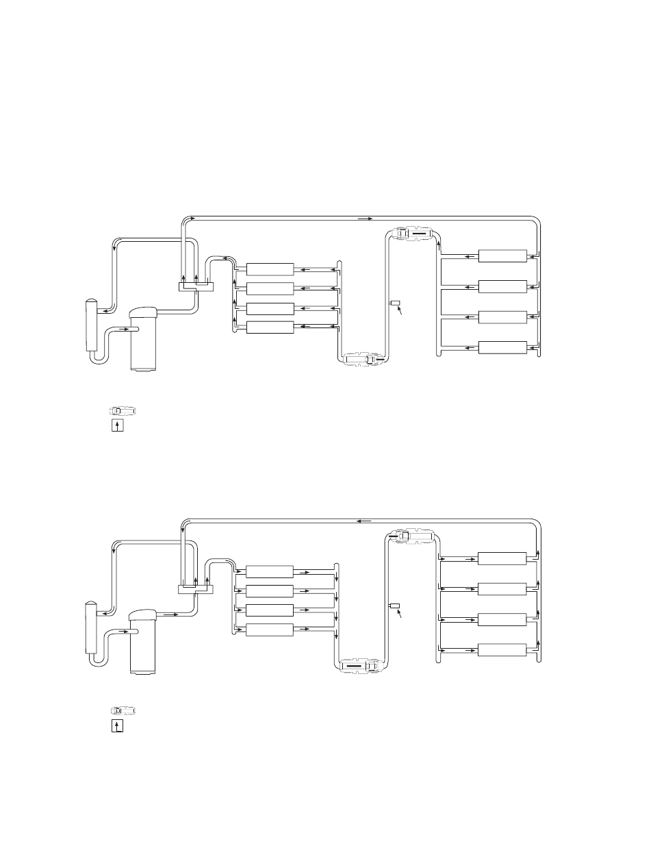
Fig. 22—Typical Heat Pump Operation, Cooling Mode
1. Hot gas from compressor flows through the 4-way valve and is directed to the outdoor coil. It is then condensed and subcooled through the coil circuits. Refrigerant leaves
the outdoor coil by way of the OD Accurater in the bypass position to the liquid line.
2. The refrigerant then feeds the indoor coil through the ID Accurater device in the metering position and distributes to each circuit.
3. Each circuit evaporates the refrigerant and the circuits are combined in the indoor coil header.
4. The refrigerant then flows through the 4-way valve, accumulator, and back to the compressor.
C99028
COMPRESSOR
A
CCUMULA
T
O
R
OUTDOOR COIL
INDOOR COIL
LCS
LEGEND
LCS – Loss of Charge Switch
Accurater
®
Metering Device
Arrow indicates direction of flow
Metering
Position
Bypass
Position
Fig. 21—Typical Heat Pump Operation, Heating Mode
1. Hot gas from compressor flows through the 4-way valve and is directed to the indoor coil. It is then condensed and subcooled through the coil circuits and then leaves
the indoor coil by way of the ID Accurater in the bypass position to the liquid line.
2. The refrigerant then feeds the outdoor coil through the OD Accurater device in the metering position and distributes to each circuit.
3. Each circuit evaporates the refrigerant and the circuits are combined in the outdoor coil header.
4. The refrigerant then flows through the 4-way valve, accumulator, and back to the compressor.
C99027
COMPRESSOR
A
CCUMULA
T
O
R
OUTDOOR COIL
INDOOR COIL
LCS
LEGEND
LCS – Loss of Charge Switch
Accurater
®
Metering Device
Arrow indicates direction of flow
Bypass
Position
Metering
Position
16