Custom programming options, Minimum drive, Dead band – Novak Brushless Speed Control: GTB 3 Track Guide (55-1747P-1.1) User Manual
Page 3: Reverse, Motor rotation, Voltage cut-off, Trans/reciever rate, Hall sensor test, Restoring factory defaults
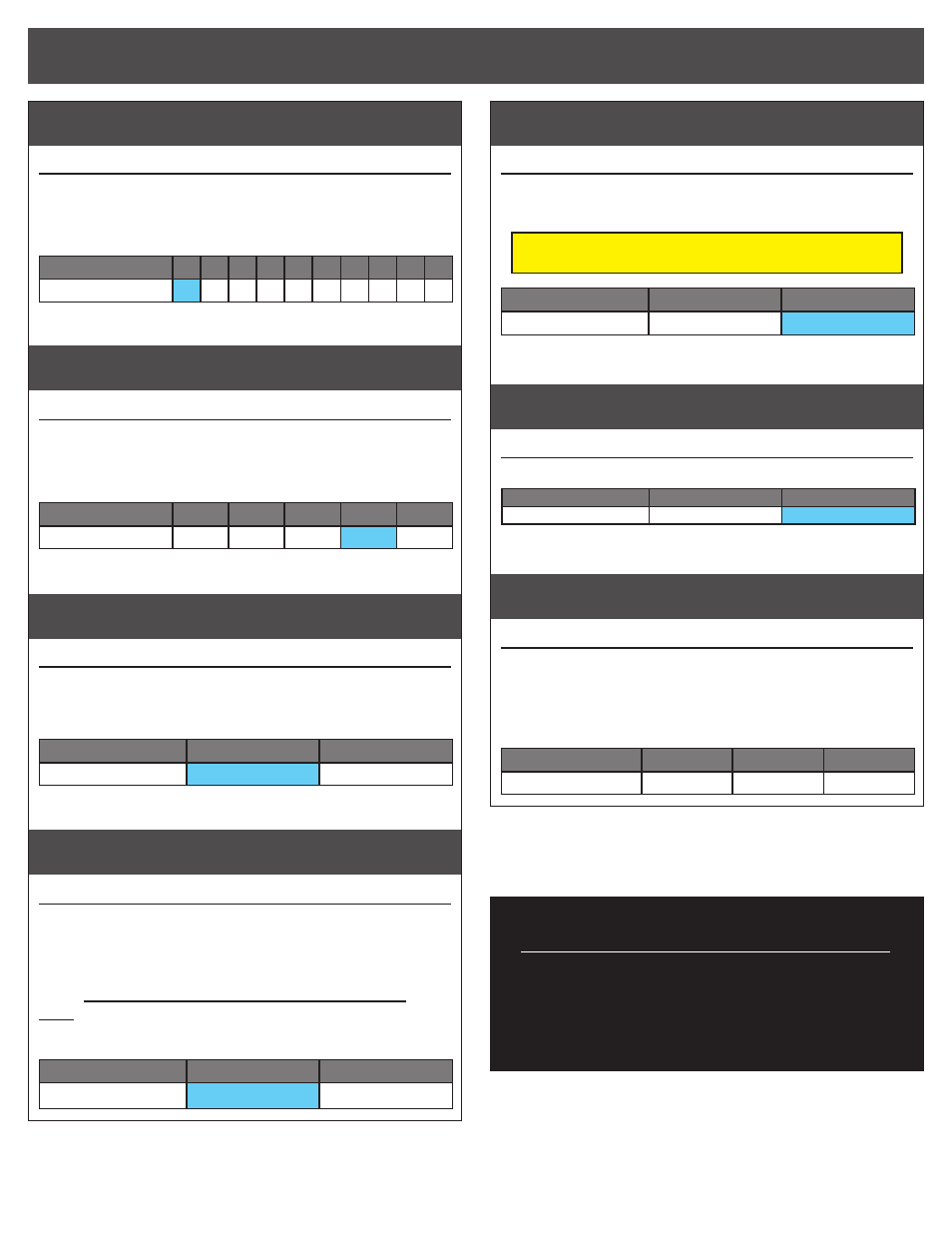
minimum drive
#6 MINIMUM DRIVE SETTINGS
(1 of 10)
BLUE & YELLOW LEDs
Amount of forward drive applied with first pulse of transmitter throttle information.
>> Increasing this setting starts the forward drive at a stronger level.
This is useful to compensate for heavier vehicles to minimize the
amount of trigger throw required before effective drive is applied.
Setting
(# of flashes)
1
2
3
4
5
6
7
8
9 10
Minimum Drive (%):
0
1
2
3
4
6
8 10 12 15
dead band
#7 DEAD BAND SETTINGS
(1 of 5)
BLUE & RED LEDs
The space between Minimum Brake and Minimum Drive, with Neutral in the middle.
>> Increasing this setting increases amount of ‘free play’, or distance the
transmitter’s trigger must move before forward drive or braking begins.
This is useful for triggers that don’t center accurately or have worn pots.
Setting
(# of flashes)
1
2
3
4
5
Dead Band (%):
2
3
4
5
8
reverse
#8 DRIVE/BRAKE MODE SELECTION
(1 of 2) BLUE & GREEN LEDs
>> Changing this setting activates or deactivates the ESC’s motor
reversing functionality. When OFF, the ESC has forward and brakes
only. When ON, the ESC has forward with brakes, then reverse with
a second push of trigger after braking to a slow speed.
Setting
(# of flashes)
1
2
Reverse:
OFF
ON
motor rotation
#9 MOTOR ROTATION SELECTION
(1 of 2) BLUE & WHITE LEDs
>> Changing this setting changes the rotational direction of the
motor’s output/pinion shaft. Counter-clockwise rotation is the
standard in most remote control vehicles. For optimal motor
performance, use counter-clockwise rotation instead of reversing the
transmitter’s throttle channel throw.
Counter-clockwise rotation is standard in most vehicles.
Note:
Novak Spec & Mod motors come factory-timed to 30° timing
and are optimized for primarily forward-only operation when the
motor is operating in the CCW rotation.
Setting
(# of flashes)
1
2
Rotation Direction:
CCW
Q
CW
P
voltage cut-off
#10 VOLTAGE CUT-OFF
(1 of 2)
BLUE-YELLOW-RED-GREEN LEDs
>> Changing this setting enables or disables the built-in Auto-Detect
Smart Stop voltage cut-off circuitry, and also sets the voltage cut-off
point based on the number of cells in the vehicle’s main battery pack.
DO NOT USE LiPo BATTERIES WITH THE ESC’S
VOLTAGE CUT-OFF CIRCUITRY TURNED OFF
Setting
(# of flashes)
1
2
Voltage Cut-Off Type:
OFF
(NiMH/NiCd)
LiPo
trans/reciever rate
#11 RECEIVER RATE SELECTION
(1 of 2)
RED & GREEN LEDs
>> Selects type of transmitter/receiver rate ESC will work with.
Setting
(# of flashes)
1
2
Radio System Mode:
M12 SSR MODE
STD RATE Rx MODE
hall sensor test
#12 MOTOR SENSOR TEST
Blinking BLUE LED
>> This is a diagnostic feature that allows you to easily check the
functionality of your brushless motor’s hall effect sensors & sensor
harness and its connections at the speed control and motor. Once
activated, slowly rotate the motor’s output/pinion shaft and the
appropriate LED will light up if a signal is received for its sensor
in the motor. Refer to ‘MOTOR HALL SENSOR TEST’ section.
Motor Hall Sensor
A
B
C
LED Color:
BLUE
YELLOW
RED
restoring factory defaults
Every time the speed control’s
One-Touch Programming is performed,
the ESC will automatically revert back
to the factory default settings.
Note: ESC Parameter values are subject to change due to ongoing development. Refer to our web site for updated values and more information on ESC parameters.
w w w . t e a m n o v a k . c o m
CUSTOM programmiNG options