Custom programming options, Drag brake, Minimum brake – Novak Brushless Speed Control: GTB 3 Track Guide (55-1747P-1.1) User Manual
Page 2: Brake power, Drive frequency, Brake frequency, Esc software flow chart
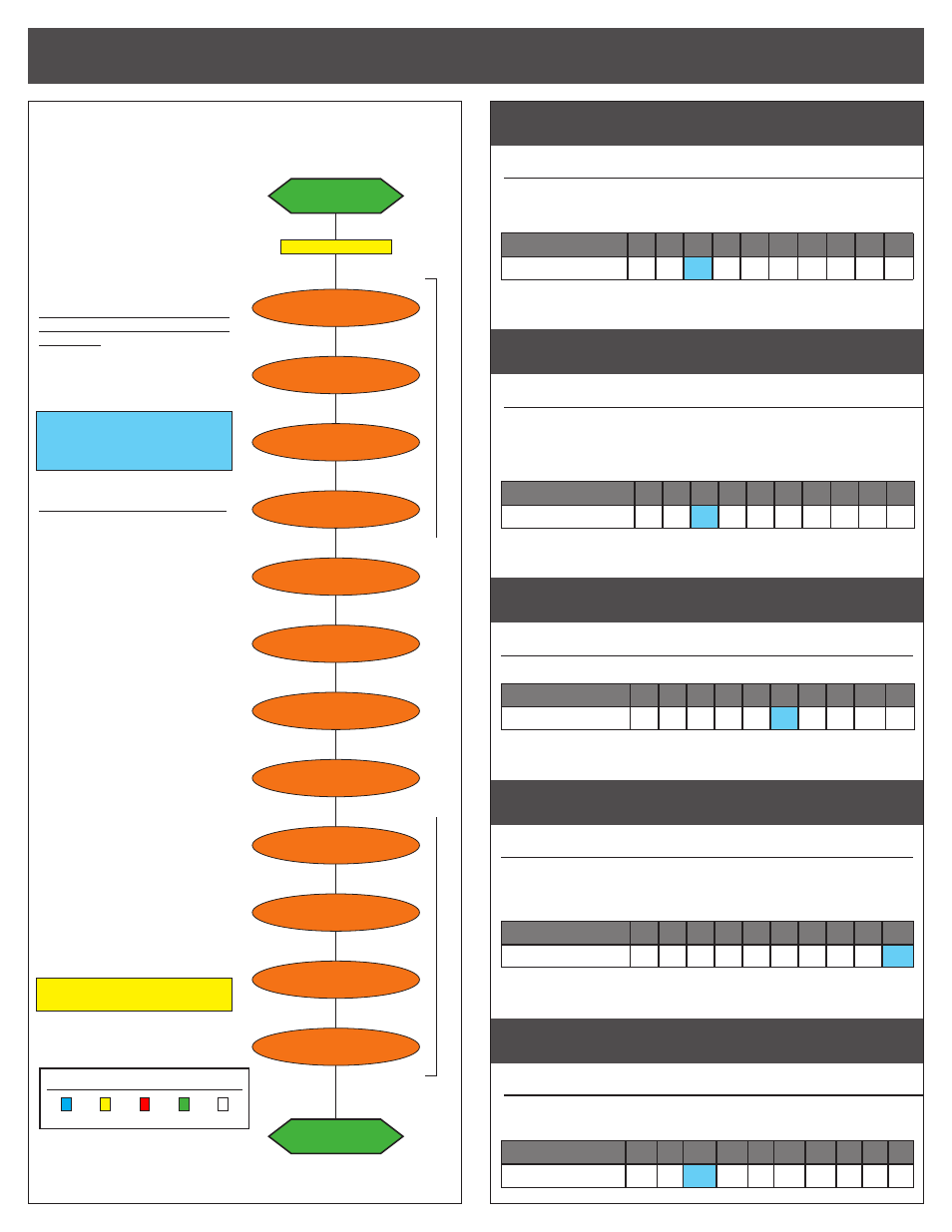
ESC STATUS LED ORDER:
BLUE YELLOW RED
GREEN WHITE
CUSTOM programmiNG options
esc software flow chart
This speed control features many
parameters that can be customized
to fine-tune the ESC’s feel &
response to your liking.
The flow chart below and the
adjustment steps to the right
describe the different parameters
and how they effect the ESC.
One-Touch Programming must be
completed before customization of
parameters, as all ESC parameters
are defaulted back to the factory
settings whenever the One-Touch
Programming is performed.
DEFAULT SETTINGS FOR
THE ESC PARAMETERS ARE
LISTED IN BOLD IN THE
TABLES TO THE RIGHT
TO CHANGE PARAMETER SETTINGS:
1. CONNECT THE ESC TO A
CHARGED BATTERY PACK,
RECEIVER, AND MOTOR’S
SENSOR HARNESS.
2. TURN ON TRANSMITTER.
3. SLIDE THE ESC’s ON/OFF
SWITCH TO ‘ON’ POSITION
4. WITH ESC AT NEUTRAL, PRESS
& HOLD SET BUTTON
Release ESC’s SET button once LEDs
are lit for the desired setting.
To skip a parameter, continue
to press & hold SET button until
desired parameter is reached.
5. SELECT PARAMETER VALUE
LED flashes to indicate active
setting (refer to tables at right).
Quick press & release SET button
to select desired setting.
6. PRESS & HOLD SET BUTTON
TO STORE NEW SELECTION
When SET button is pressed and
held for about 1 second,
the
new selection is stored in ESC’s
memory—Status LEDs will scroll across
to indicate ESC is exiting programming
& ESC returns to neutral.
There is no time constraint during
selection of custom parameters.
drag brake
#1 DRAG BRAKE SETTINGS
(1 of 10)
BLUE LED
Amount of braking being applied while transmitter is at neutral. AKA ‘coast’ brakes.
>> Increasing this setting makes the motor slow down more without
pushing the transmitter’s trigger into the brake/reverse direction.
Setting
(# of flashes)
1
2
3
4
5
6
7
8
9 10
Drag Brake (%):
0
3
6
9 12 15 18 21 24 30
minimum brake
#2 MINIMUM BRAKE SETTINGS
(1 of 10)
YELLOW LED
Amount of braking applied with first pulse of transmitter braking information sent.
>> Increasing this setting starts the braking at a stronger level.
This is useful to compensate for heavier vehicles to minimize the
amount of trigger throw required before effective braking is applied.
Setting
(# of flashes)
1
2
3
4
5
6
7
8
9 10
Minimum Brake (%):
0
3
6
9 12 15 18 21 24 30
brake power
#3 BRAKE POWER SETTINGS
(1 of 10)
RED LED
>> This setting changes the maximum braking power at full brake throw.
Setting
(# of flashes)
1
2
3
4
5
6
7
8
9
10
Drive Freq.
(KHz)
:
10 20 30 40 50 60 70 80 90 100
DRIVE FREQUENCY
#4 DRIVE FREQUENCY SETTINGS
(1 of 10)
GREEN LED
How the ESC’s throttle response feels with respect to the transmitter’s trigger input.
>> Increasing the Drive Frequency makes the throttle response
feel smoother and more controllable.
Setting
(# of flashes)
1
2
3
4
5
6
7
8
9
10
Drive Freq.
(KHz)
:
8 10 12 14 16 21 23 26 32 36
BRAKE FREQUENCY
#5 BRAKE FREQUENCY SETTINGS
(1 of 10)
WHITE LED
How the ESC’s braking response feels with respect to the transmitter’s trigger input.
>> Increasing Frequency makes the brakes feel smoother/more controllable.
Setting
(# of flashes)
1
2
3
4
5
6
7
8
9 10
Brake Freq. (KHz):
1.5 2 2.2 2.5 3 3.5 4.5 6
7
8
@NEUTRAL
RED LED on solid
DRAG/HILL BRAKE
BLUE
DEAD BAND
BLUE & RED
REVERSE
BLUE & GREEN
MIN. DRIVE
BLUE & YELLOW
MIN. BRAKE
YELLOW
press & hold SET button
continue holding ESC’
s SET button to skip steps here
VOLTAGE CUT-OFF
BLUE-YELLOW-RED-GREEN
MOTOR ROTATION
BLUE & WHITE
BRAKE POWER
RED
BRAKE FREQ.
WHITE
DRIVE FREQ.
GREEN
TRANS./REC RATE
RED & GREEN
HALL SENSOR TEST
Blinking BLUE
@NEUTRAL
RED LED on solid