Custom programming options, Timing level, Timing rpm range – Novak Brushless Speed Control: Crusher Field Guide (Standard Modes) --- Simple-Tuner Version ESC (3) User Manual
Page 3: Brake power, Dead band, Drive frequency, Minimum drive, Reverse, Motor rotation, Voltage cut-off
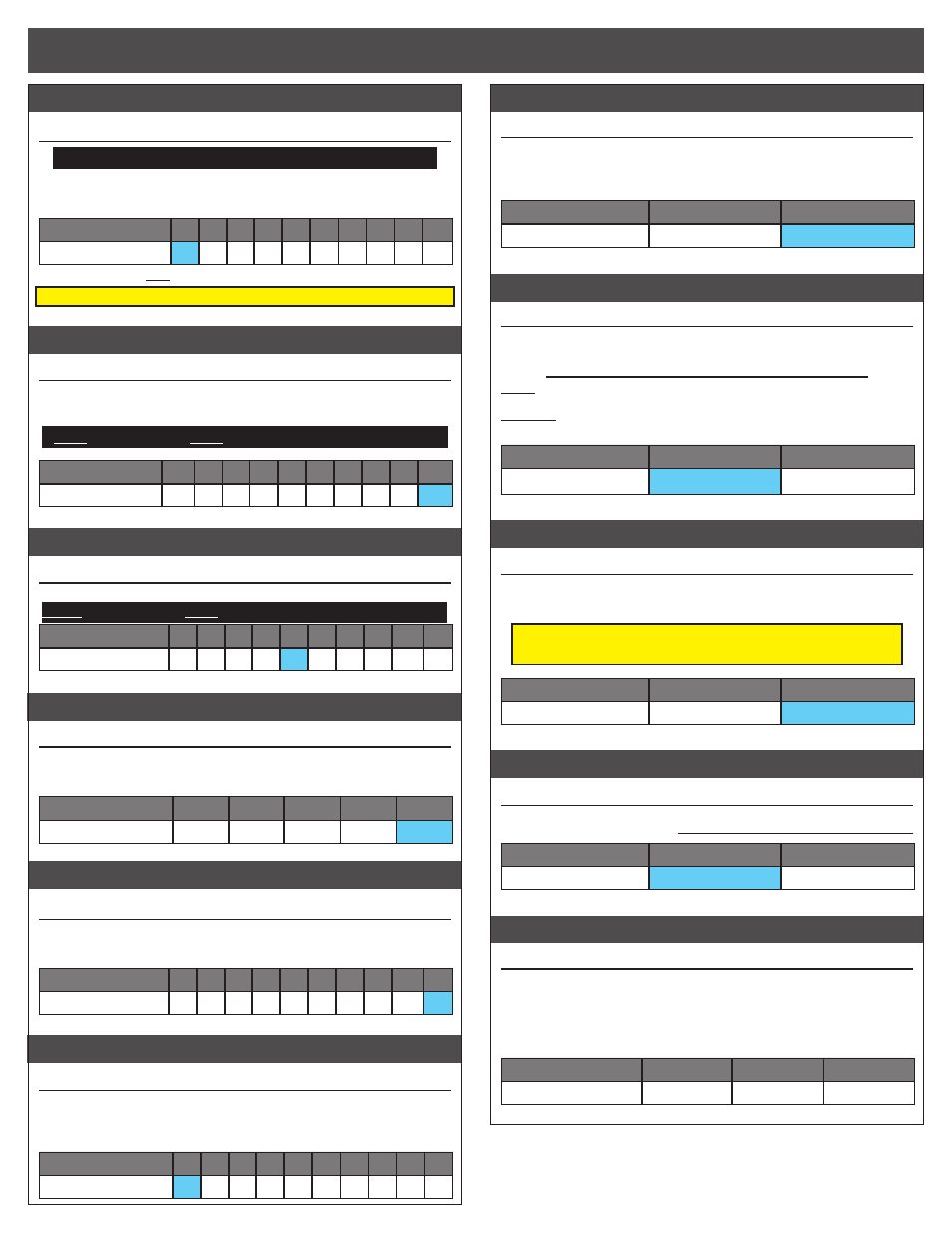
TIMING level
#5 TIMING LEVEL SETTINGS
/ BOOST TIMING
GREEN LEd
WITh sTANdARd (non-Crawler) BRushLEss MOTORs:
The maximum degrees of Dynamic Timing Advance applied to the motor.
>> Increasing this setting increases the maximum amount of electronic
timing that can be applied to the motor within the timing RPM range.
Setting
(# of flashes)
1
2
3
4
5
6* 7* 8* 9* 10*
Timing Level
(degrees):
0 10 15 18 20 25 28 30 33 35
•WARNING: DO NOT FREE-REV MOTOR TO CHECk TIMING SETTINGS•
*Timing Levels 6-10 produce excessive heating & must be used with caution.
TIMING rpm range
#6 TIMING RPM RANGE SETTINGS
WhITE LEd
The RPM range during which Dynamic Timing Advance is applied.
>> Decreasing this setting lowers the RPM trip points at which the
electronic motor timing advancement comes on (making it more agressive).
Note: This setting is ONLY available in non-Crawler Modes.
Setting
(# of flashes)
1
2
3
4
5
6
7
8
9
10
RPM Set Points:
Low 2
3
4
5
6
7
8
9 High
brake power
#7 BRAkE POWER SETTINGS
(1 of 10)
BLuE & YELLOW LEds
>> This setting changes the maximum braking power at full brake throw.
Note: This setting is ONLY available in non-Crawler Modes.
Setting
(# of flashes)
1
2
3
4
5
6
7
8
9
10
Drive Freq.
(KHz)
:
10 20 30 40 50 60 70 80 90 100
dead band
#8 DEAD BAND SETTINGS
(1 of 5)
BLuE & REd LEds
The space between Minimum Brake and Minimum Drive, with Neutral in the middle.
>> Increasing this setting increases amount of ‘free play’, or distance the
transmitter’s trigger must move before forward drive or braking begins.
Setting
(# of flashes)
1
2
3
4
5
Dead Band (%):
2
3
4
5
8
drive frequency
#9 DRIVE FREQUENCY SETTINGS
(1 of 10) BLuE & GREEN LEds
How the ESC’s throttle response feels with respect to the transmitter’s trigger input.
>> Increasing the Drive Frequency makes the throttle response feel
smoother and more controllable.
Setting
(# of flashes)
1
2
3
4
5
6
7
8
9
10
Drive Freq.
(KHz)
:
8 10 12 14 16 21 23 26 32 36
minimum drive
#10 MINIMUM DRIVE SETTINGS
(1 of 10)
BLuE & WhITE LEds
Amount of forward drive applied with first pulse of transmitter throttle information.
>> Increasing this setting starts the forward drive at a stronger level.
This is useful to compensate for heavier vehicles to minimize the
amount of trigger throw required before effective drive is applied.
Setting
(# of flashes)
1
2
3
4
5
6
7
8
9 10
Minimum Drive (%):
0
1
2
3
4
6
8 10 12 15
reverse
#11 DRIVE/BRAkE MODE SELECTION
(1 of 2) BLuE-YELLOW-REd LEds
>> Changing this setting activates or deactivates the ESC’s motor
reversing functionality. When OFF, the ESC has forward and brakes
only. When ON, the ESC has forward with brakes, then reverse with a
second push of trigger after braking to a slow speed.
Setting
(# of flashes)
1
2
Reverse:
OFF
ON
motor rotation
#12 MOTOR ROTATION SELECTION
(1 of 2) BLuE-YELLOW-GREEN LEds
>> Changing this setting changes the rotation direction of the motor’s
output/pinion shaft.
Counter-clockwise rotation is standard in most vehicles.
Note:
Novak Spec & Mod motors come factory-timed to 30° timing
and are optimized for primarily forward-only operation and the ESC
WILL NOT apply Boost Timing to these motors when operating in CW
rotation. Do NOT operate Non-Crawler Motors at 0° Timing.
Setting
(# of flashes)
1
2
Rotation Direction:
CCW
q
CW
p
voltage cut-off
#13 VOLTAGE CUT-OFF
(1 of 2)
BLuE-YELLOW-WhITE LEds
>> Changing this setting enables or disables the built-in Auto-Detect
Smart Stop voltage cut-off circuitry, and also sets the voltage cut-off
point based on the number of cells in the vehicle’s main battery pack.
DO NOT USE LiPo BATTERIES WITH THE ESC’S
VOLTAGE CUT-OFF CIRCUITRY TURNED OFF
Setting
(# of flashes)
1
2
Voltage Cut-Off Type:
OFF
(NiMH/NiCd)
LiPo
data reset
#14 DEFAULT DATA RESET
YELLOW & GREEN LEds
>> This feature resets the ESC’s adjustable parameters to factory default
values for all throttle profiles. select setting #2 then Push & hold to REsET.
Setting
(# of flashes)
1
2
Data Reset:
kEEP DATA
RESET ALL DATA
hall sensor test
#15 MOTOR SENSOR TEST
Blinking BLuE LEd
>> This is a diagnostic feature that allows you to easily check the func-
tionality of your brushless motor’s hall effect sensors & sensor harness
and its connections at the speed control and motor. Once activated,
slowly rotate the motor’s output/pinion shaft and the appropriate LED
will light up if a signal is received for its sensor in the motor. Refer to
‘MOTOR hALL sENsOR TEsT’ section.
Motor hall Sensor
A
B
C
LED Color:
BLUE
YELLOW
RED
w w w . t e a m n o v a k . c o m
CUSTOM programmiNG options
Note: ESC Parameter values are subject to change due to ongoing de-
velopment. Refer to the DOWNLOADS section of our website for updated
versions of the Crusher Field Guide.