Custom programming options, Drive mode, Drag brake – Novak Brushless Speed Control: Crusher Field Guide (Standard Modes) --- Simple-Tuner Version ESC (3) User Manual
Page 2: Minimum brake, Brake frequency, Simple-tuner flow chart, Esc status led order
CUSTOM programmiNG options
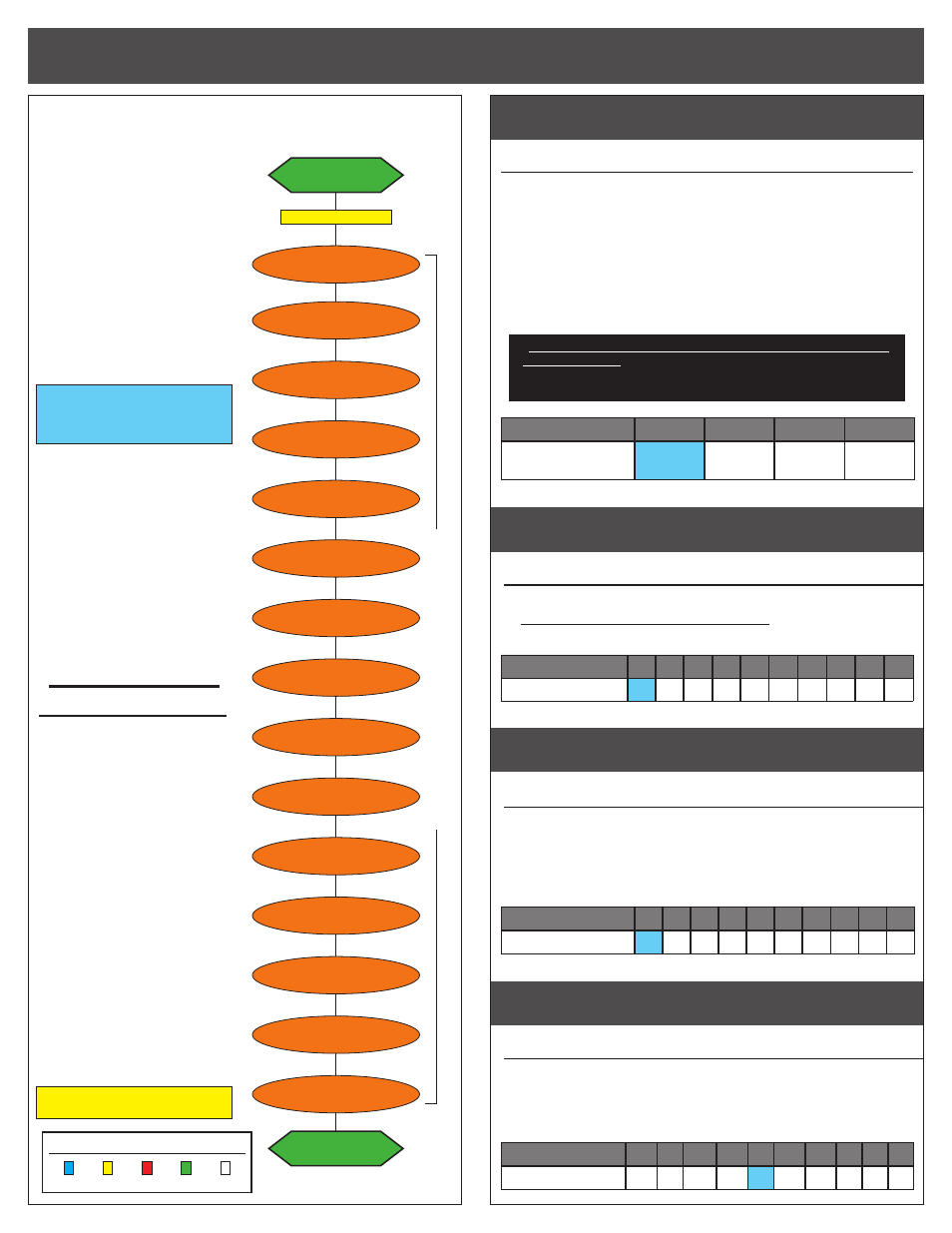
simple-tuner flow chart
drive modE
#1 DRIVE MODE SELECTION
(1 of 3)
BLuE-REd-WhITE LEds
Drive mode being used. Refer to ‘THROTTLE PROFILES’ section on page 1
for the parameter default values for each throttle profile.
>> Setting 1 = BASHER MODE-- standard forward/brake/reverse
operation, optional drag brake at neutral, Novak smart-Braking with
double-pump of trigger for reverse. (no timing w/Novak crawler motors).
>> Settings 2 = RACER MODE--same operation as Basher Mode but
with modified parameter values for racing, including no reverse.
>> Setting 3 = TIMING TEST MODE--same operation as Racer Mode
but with mild timing level and low power brakes.
*This FIELd GuIdE is specific to Racing/Bashing set-ups using
standard motors. If you are planning on operating in the Rock
Crawler mode (Profile 4) with Novak crawler motors, download
the Crusher “Rock Crawler Mode” Field Guide.
Setting
(# of flashes)
1
2
3
4
Drive Mode
(motor)
:
Basher
Racer
Timing
Test
Crawler*
drag brake
#2 DRAG BRAkE SETTINGS
(1 of 10)
BLuE LEd
Amount of braking being applied while transmitter is at neutral.
>> Settings 1-10 are Standard Drag Brake settings--drag braking
levels for racing or sport-style driving
(setting #1 applies no braking at neutral).
Setting
(# of flashes)
1
2
3
4
5
6
7
8
9 10
Drag Brake (%):
0
3
6
9 15 20 25 30 40 50
minimum brake
#3 MINIMUM BRAkE SETTINGS
(1 of 10)
YELLOW LEd
Amount of braking applied with first pulse of transmitter braking informa-
tion sent.
>> Increasing this setting starts the braking at a stronger level.
This is useful to compensate for heavier vehicles to minimize the
amount of trigger throw required before effective braking is applied.
Setting
(# of flashes)
1
2
3
4
5
6
7
8
9 10
Minimum Brake (%):
0
3
6
9 12 15 18 20 30 45
BRAKE FREQUENCY
#4 BRAkE FREQUENCY SETTINGS
(1 of 10)
REd LEd
How the ESC’s braking response feels with respect to the transmitter’s trig-
ger input.
>> Increasing Brake Frequency makes the brakes feel smoother
and more controllable.
Setting
(# of flashes)
1
2
3
4
5
6
7
8
9 10
Brake Freq. (KHz):
1.5 2 2.2 2.5 3 3.5 4.5 6
7
8
@NEUTRAL
RED LED on solid
TIMING LEVEL
GREEN
RPM RANGE
WHITE
DRAG BRAKE
BLUE
DEAD BAND
BLUE & RED
REVERSE
BLUE-YELLOW-RED
MOTOR ROTATION
BLUE-YELLOW-GREEN
MIN. DRIVE
BLUE & WHITE
MIN. BRAKE
YELLOW
press & hold SET button
continue holding ESC’
s SET button to skip steps here
BRAKE POWER
BLUE & YELLOW
DRIVE MODE
BLUE-RED-WHITE
VOLTAGE CUT-OFF
BLUE-YELLOW-WHITE
DATA RESET
YELLOW & GREEN
BRAKE FREQ.
RED
DRIVE FREQ.
BLUE & GREEN
HALL SENSOR TEST
Blinking BLUE
@NEUTRAL
RED LED on solid
This speed control features Novak’s
Simple-Tuner programming interface
with numerous ESC parameters that
can be customized to fine-tune the
ESC’s feel & response to your liking.
The flow chart and the descriptions
to the right show the order of the
different parameters and how they
effect the ESC’s feel or response.
One-Touch Set-Up (page 1) should
be completed before customization
of ESC parameters that are based
off percentages of the trigger’s
full-throttle and full-brake position.
Note: ESC parameters do NOT default
back to the factory settings when the
One-Touch Programming is performed.
THE SETTINGS LISTED IN BOLD IN
THE PARAMETER ADJUSTMENT
TABLES ARE THE DEFAULT
SETTINGS FOR PROFILE #1
The sequence that the status LEDs
of the ESC goes through in the
Simple-Tuner software is easier
than ever to follow. Common ESC
parameters are grouped together,
and the LEDs also light up in order
from left to right on the ESC.
The first adjustable item is the
ESC’s Drive Mode (motor type),
next comes a group of Braking
adjustments and Timing settings,
followed by 3 forward Drive
settings, and then finished up with
Reversing functionality, Motor
Rotation, LiPo ON/OFF, Data Reset,
and a motor test mode to check the
hall sensors & harness connections.
TO ChANGE PARAMETER sETTINGs:
1. CONNECT THE ESC TO A FULLY
CHARGED BATTERY PACK, A
RECIEVER, AND THE MOTOR’S
SENSOR HARNESS
2. SLIDE THE ESC’s ON/OFF
SWITCH TO ‘ON’ POSITION
3. WITH ESC AT NEUTRAL, PRESS
& HOLD SET BUTTON
Release ESC’s SET button once LEDs
are lit for the desired setting.
To skip a parameter, continue
to press & hold SET button until
desired parameter is reached.
4. SELECT PARAMETER VALUE
LED flashes to indicate active setting
(refer to tables at right). Quick press
& release SET button to select
desired setting.
5. PRESS & HOLD SET BUTTON TO
STORE NEW SELECTION
When SET button is pressed and
held for about 1 second,
the
new selection is stored in ESC’s
memory—Status LEDs will scroll across
to indicate ESC is exiting programming
& ESC returns to neutral.
There is no time constraint during
selection of custom parameters.
EsC sTATus LEd ORdER:
BLuE YELLOW REd
GREEN WhITE