Table 1: gui controls – Maxim Integrated 73M1966B User Manual
Page 9
UG_1x66B_002
73M1866B/73M1966B GUI User Guide
Rev. 1.1
9
The bottom half of the Register Access screen shows the status of the entire 73M1x66B register set (in
hex) and provides information and parameter controls.
Table 1 describes these controls.
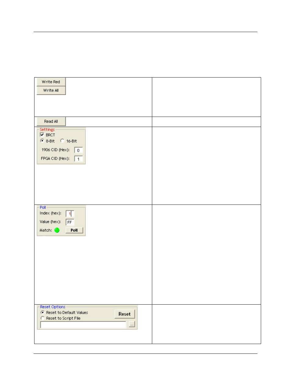
Table 1: GUI Controls
Click Write Red to write all red values in the
bottom half of the screen. Values become red
when changed by checking or un-checking boxes
in the top half of the screen. Click Write all to
write all values (both read and black). After
writing values, all values become black and
remain black until another box is checked.
Click to read all current values from the board.
Select BRCT (BroadCasT) to send the same
control data to all the 73M1966Bs in a daisy
chain, ignoring their individual addresses. When
using the 73M1966B in daisy chain mode, it is
necessary to set the address of the 73M1966B
that is being accessed. Each board has a
73M1906B and FPGA address. For example,
the next downstream daisy chained 73M1966B
board will have an address for its 73M1906B of
03h and its FPGA address will be 04h, and so
on. See Section 5 of the 73M1866/73M1966
Data Sheet for a description of the control byte
and the BRCT bit. The radio buttons allow the
selection of 8-bit or 16-bit SPI operations.
Implements the POLL function as described in
Section 6.1 of the 73M1866B/73M1966B Data
Sheet. The Index field corresponds to the INDX
field (Register 0x19[3:0]). The Value field
corresponds to the POLVAL field (Register
0x1F[7:0]). Index is the offset address of the
register to be manually polled with the results
placed in POLVAL. The Index value ranges from
0 to 6 only. Index 0 refers to Register 0x12,
Index 1 to Register 0x13, etc. The Value field
returns the content of the register corresponding
to the specified Index. Enter the index in the
Index box. Select Poll. When this register is
polled, the value is read back in the Value box.
After selecting Poll, a red dot next to Match
means that the register was not properly written.
A green dot proves that the register was properly
written.
Sets the registers to a default operating
configuration. This is not the same as the default
register settings after the 73M1x66 goes through
a device reset. The default register settings may
not be appropriate for all PCM test sets, so you
may define your own default operating
conditions.