2 using the gui, Using the gui, Figure 1: register access screen – r00-r09 tab – Maxim Integrated 73M1966B User Manual
Page 8
73M1866B/73M1966B GUI User Guide
UG_1x66B_002
8
Rev. 1.1
2.2 Using the GUI
The 73M1866B or 73M1966B Demo Board must be set up before using the GUI. See the
73M1866B/73M1966B Demo Board User Manual for setup procedures.
To start the GUI using Windows XP, select Start
All Programs Teridian Teridian 73M1966B.
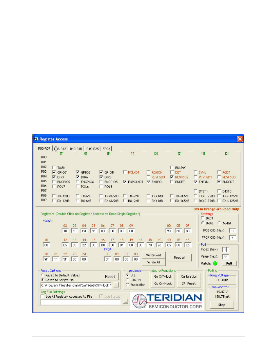
The Register Access screen appears (see Figure 1). The screen is divided into a top half and a bottom
half. The first row of the top half consists of five tabs: R00-R09, R0A-R12, R13-R1B, R1C-R25 and FPGA.
The R00-R09 tab displays the register map for the first ten 73M1966B registers. The contents of each
named bit can be changed by checking or un-checking the box next to it. A checked box means that the
bit is set to 1 and an un-checked box means that the bit is set to 0. As boxes are checked and
unchecked, the values in the bottom half reflect the changes and turn red. Select new values by checking
and un-checking register bits. Click the Write Red button to set the values. Notice that after writing the
values, all previously red values turn black. Polling can be done by double clicking on the lower register
map for the register you are interested in or using the “Read All” radio button.
Figure 1: Register Access Screen – R00-R09 Tab