1 jumper position changes, 2 device configuration – Maxim Integrated 78M6610+LMU Evaluation Kit User Manual
Page 21
78M6610+LMU Evaluation Kit User Manual
Rev 1
21
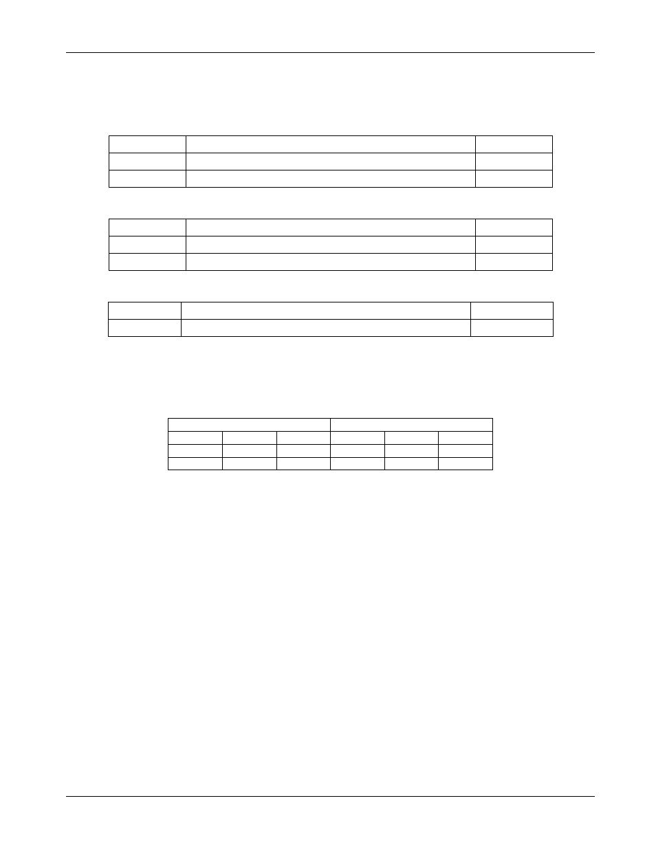
6.1.1 Jumper Position Changes
Move J23 and J24 jumpers to position CT to use CT2 and remove jumper at J9.
J23 Jumper Description
J23 Pins
Description
Jumper
1/2
Connect J15 SHUNT to 78M6610+LMU Sensor Slot 1
Installed
2/3
Connect J10 CT2+ to 78M6610+LMU Sensor Slot 1
-
J24 Jumper Description
J24 Pins
Description
Jumper
1/2
Connects J8 SHUNT to 78M6610+LMU Sensor Slot 1
Installed
2/3
Connects J10 CT2- to 78M6610+LMU Sensor Slot 1
-
J9 Jumper Description
J9 Pins
Description
Jumper
1/2
Connect AC Neutral to V3P3A (chip reference)
Installed
6.1.2 Device Configuration
Use the Configuration tab to map the sensors as shown in the table below. Re-enter the gain value for CT2
(located on bottom of board) into the S1_GAIN register if needed.
Voltage
Current
VA
S0
0
IA
0
S3
VB
0
S2
IB
-S1
-S3
VC
S0
-S2
Pre-Amp
1X S1
1X S3
Note: The values for VC and IB will not be displayed correctly on the Power tab of the provided GUI due to the
increased full-scale values of VC and IB. Reported results for measurements derived from VC and IB will be
one-half the expected magnitude.