2 isolated rs-485 interface, 3 isolated uart, i2c, spi interfaces, Rs-485 interface – Maxim Integrated 78M6610+LMU Evaluation Kit User Manual
Page 12
78M6610+LMU Evaluation Kit User Manual
12
Rev 1
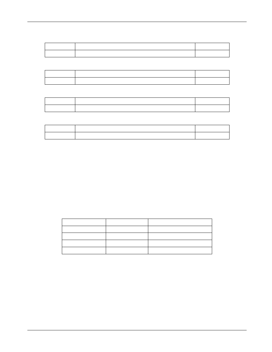
J27 Jumper Description
J27 Pins
Description
Default
1/2
Enable on-board RS485 termination resistor
-
J28 Jumper Description
J28 Pins
Description
Default
1/2
Connect USB Controller to isolation IC (U7)
Installed
J29 Jumper Description
J29 Pins
Description
Default
1/2
Connect USB Controller to isolation IC (U7)
Installed
J38 Jumper Description
J38 Pins
Description
Default
1/2
Enable on-board RS485 termination resistor
-
4.2 Isolated RS-485 Interface
The board also includes an isolated RS-485 interface as an alternative to the USB interface. The
78M6610+LMU serial UART is connected to the RS-485 transceiver. Refer to the IC data sheet for details on
the serial protocol.
Move J12, J17, and J18 jumpers from position 1-2 to position 2-3 to connect the RS-485 transceiver
instead of the USB controller.
The USB cable provides power to the EV board when connected to the PC. If the USB cable not being used
+5VDC power must be provided at J16, pins 1 and 6 (+5V and ground, respectively). Do not supply power to
JJ16, pin1 AND connect the USB cable to the PC.
J22 RS-485 Connector Pin Assignment
J22 Pin Number
Pin Name
Pin Description
1
+5VDC
Connect to external source
2
Data - P
Tri-state, Bi-directional
3
Data - N
Tri-state, Bi-directional
4
GND
Connect to external source
4.3 Isolated UART, I
2
C, SPI Interfaces
The native host interfaces of the 78M6610+LMU are made available on the isolated side of the barrier at J16.