Introduction, 1 introduction – Maxim Integrated 6613_OMU_2+2S_URT_V100 User Manual
Page 5
UG_6613_ 060
6613_OMU_2+2S_URT_V1_00 Firmware Description Document
Rev. 1.1
5
1 Introduction
This document describes the 6613_OMU_2+2S_URT_v100 firmware, which is used with the Teridian
78M6613 power and energy measurement IC. This firmware provides simple methods for calibration and
access to measurement data such as Instantaneous Power, Voltage, Current, Power Factor, and Line
Frequency. It is specifically developed for measurement of up to two single phase loads with the
following key features:
• Optimized for using current shunt resistors with analog inputs A0, A2 are configured as Voltage input
and input A1,A3 are configured as Current inputs.
• Phase error calibration routine included for use of current transformers and/or maintaining accuracy
over non-ideal power factors.
• Low-latency SAG status pin for sub-cycle AC fault detection.
• UART (RS232) host interface (Command Line Interface).
All measurement calculations are computed by the 78M6613 and communicated to the host processor
over a serial interface (UART0) on the TX and RX pins of the 78M6613 device. Digital IOs utilized by this
firmware include:
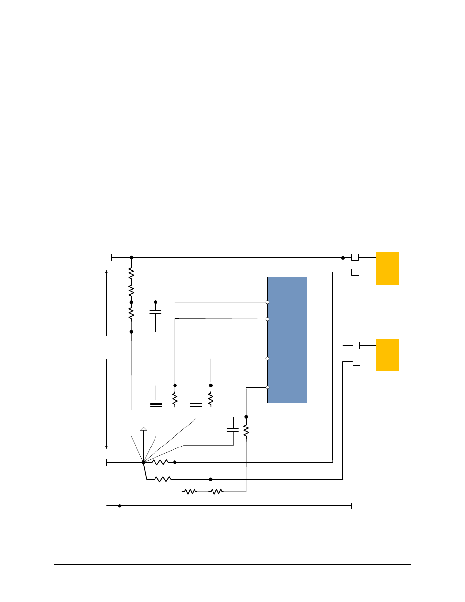
Figure 1 shows a simplified connection diagram of the 78M6613 (emulator connections, decoupling
capacitors and 3.3VDC power supply are omitted in this diagram).
Shunt 1
NEUTRAL
A0
A3
750
1M
1M
100nF
A2
LOAD 1
78M6613
V3P3
1
4
3
2
INLET
LINE
Shunt 2
LOAD 2
A1
750
100nF
750
100nF
1M
1M
EARTH
750
Figure 1: Typical 78M6613 Connection Diagram for 6613_OMU_2+2S_URT_v100