Configuration parameter entry, Mpu parameters, Table 4: mpu parameters – Maxim Integrated 6613_OMU_2+2S_URT_V100 User Manual
Page 29: Table 4, 6 configuration parameter entry, 1 mpu parameters
UG_6613_ 060
6613_OMU_2+2S_URT_V1_00 Firmware Description Document
Rev. 1.1
29
6 Configuration Parameter Entry
6.1 MPU Parameters
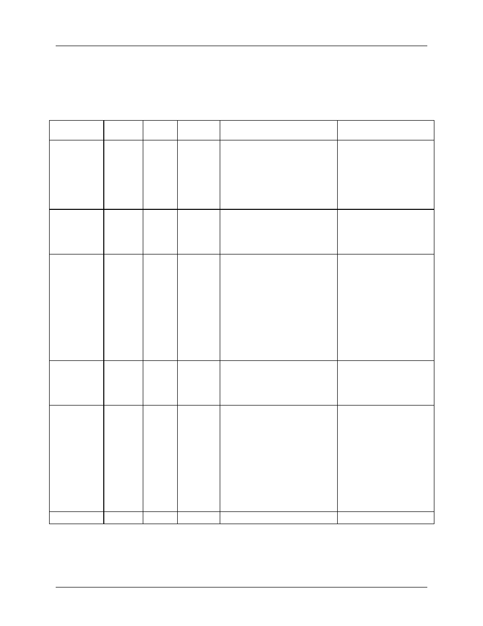
Table 4 lists the MPU parameters configurable by the 6613_OMU_2+2S_URT_v100 Firmware.
Table 4: MPU Parameters
MPU
Parameter
Location
(hex)
LSB
Default
Comment
Example
VMAX
A0
mVrms
+471.500
External rms voltage
corresponding to 250 mVpk at the
VA input of the 78M6613. It must
be set high enough to account for
overvoltages. Usually set to
471.500 V (471.500d).
If only using a 120V
system, the user can set
VMAX A to about 2x the
maximum voltage for added
resolution. Set VMAX A to
270V:
)A0=+270.000
Starting IA
A1
mArms
+0.007
Minimum current value to be
measured on the IA input.
Currents below this value will be
ignored. Also known as CREEP
IA.
Default setting is 7 mA. If
start current on channel A
desired is 10 mA:
)A1=+0.010
IMAX A
A2
mArms
+52.000
External rms current
corresponding to 250 mVpk at the
IA input of the 78M6613.
The default is set to 52
Amps for overhead. For
added margin, in a system
using current shunts IMAX
could be changed as
follows:
IMAX= (Vpk/
√2)/R
shunt
For a 4 m
Ω current shunt
IMAX=44.19 Amps
To set IMAX A:
)A2=+44.190
Starting IB
A3
mArms
+0.007
Minimum current value to be
measured on the IB input.
Currents below this value will be
ignored. Also known as CREEP
IB.
Default setting is 7 mA. If
start current on channel A
desired is 10 mA:
)A3=+0.010
IMAX B
A4
mArms
+52.000
External rms current
corresponding to 250 mVpk at the
IB input of the 78M6613.
The default is set to 52
Amps for overhead. For
added margin, in a system
using current shunts IMAX
could be changed as
follows:
IMAX= (Vpk/
√2)/R
shunt
For a 4 m
Ω current shunt
IMAX=44.19 Amps
To set IMAX A:
)A4=+44.190
Unused
A5
–
–
Unused