2 ce parameters, Ce parameters, Table 4: ce parameters – Maxim Integrated 6613_PSU_1+1S_URT_v1_00 User Manual
Page 29
UG_6613_ 040
6613_PSU_1+1S_URT_V1_00 Firmware Description Document
Rev. 1.0
29
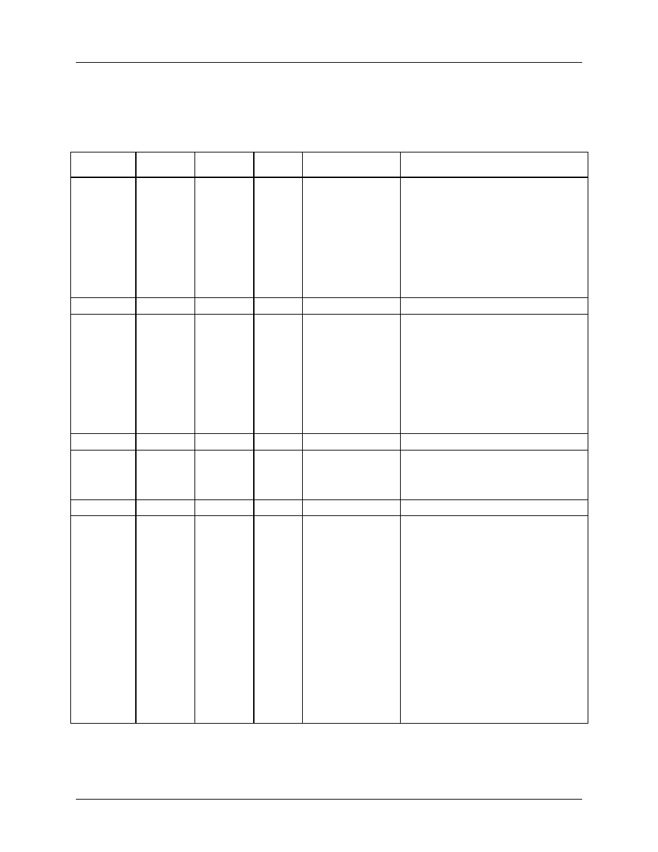
8.2 CE Parameters
Table 4 lists the CE parameters configurable by the 6613_PSU_1+1S_URT_v1_00 Firmware. The user
does not need to alter any of these parameters.
Table 4: CE Parameters
CE
Parameter
Location(
hex)
LSB
Default
Comment
Example
CAL IA
08
16384 is
the default
and is a
gain of 1.
32767 is
max giving
a gain of
2.
+13873
Gain constant for IA
input.
If current on channel A is low by 1%
scale the nominal number, 16384 by
1/(1-0.01). Number to be entered would
be 16549:
]08=+16549
If current on channel A is high by 1%
scale the nominal number, 16384 by
1/(1+0.01). Number to be entered would
be 16222:
]08=+16222
Unused
09
CAL VA
0A
16384 is
the default
and is a
gain of 1.
32767 is
max giving
a gain of
2.
+16384
Gain constant for
VA input.
If voltage on channel A is low by 1%
scale the nominal number, 16384 by
1/(1-0.01). Number to be entered would
be 16549:
]0A=+16549
If current on channel A is high by 1%
scale the nominal number, 16384 by
1/(1+0.01). Number to be entered would
be 16222:
]0A=+16222
Unused
0B
PHASE_
ADJ_IA
0C
-16384
≤
PHASE_A
DJ_IA
≤
+16384
0
Phase adjustment
=15 *
PHASE_ADJ_IA *
2
-14
(degrees)
No adjustment should be necessary
when using current shunts.
Unused
0D
CESTATE
0E
5001h
SAG CNT
Bits 15:8 –
determines the
consecutive voltage
samples below
SAG_Threshold
before a sag alarm
is declared. 255 is
the maximum
value.
Pulse gain factor
Bits 1 and 0
00 – 6x
01 – (6/64)x
10 – 96x
11 – 1.5x
]0E=5001
Selects at least 80 (50h) consecutive
voltage samples below SAG_Threshold
before SAG alarm.
Selects Pulse Gain Factor equal to 6/64
(1h)