Out of production – LAARS HP-M2 Series - Installation, Operation and Maintenance Instructions User Manual
Page 16
Page 16
LAARS Heating Systems
SECTION 6.
Electrical Connections
6A. Electrical Connections
All electrical wiring must conform to local codes
and/or the 1). National Electric Code or 2). Canadian
Electrical Code - Part 1.
The unit must be electrically grounded in
accordance with the requirements of the authority
having jurisdiction or, in the absence of such
requirement, with the 1). National Electrical Code.
ANSI/NFPA NO.70- latest edition, or the CSA
Standard C22.1 “Canadian Electrical Code - Part 1”.
Single pole switches, including those of safety
controls and protective devices must not be wired in a
grounded line.
All electrical connections are made in the field
wiring box which is located on the right side of the
unit.
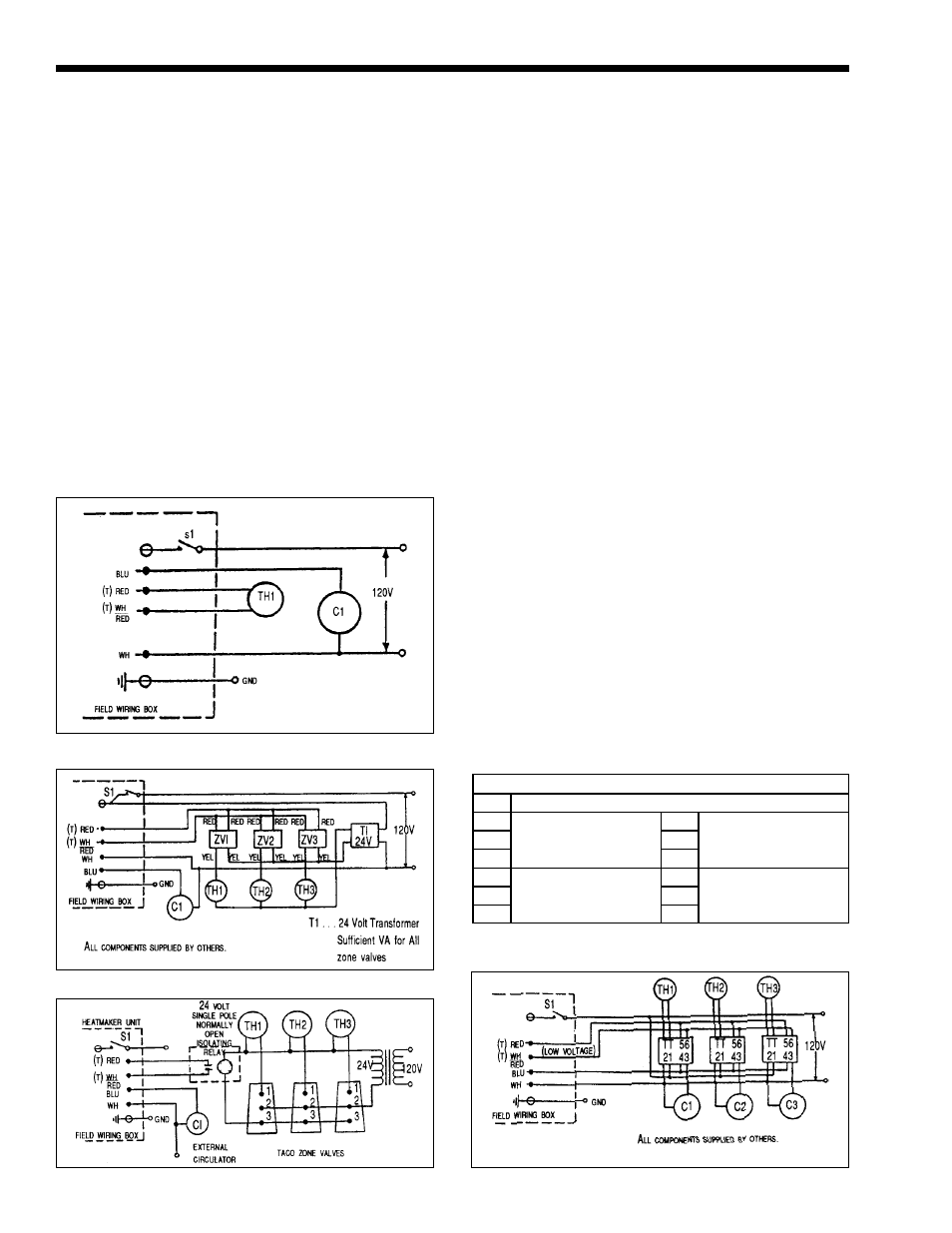
Figure 18. Single Zone.
Figure 19. Zoning with Zone Valves.
Figure 20. Zoning with 3 Wire Zone Valves.
Figure 21. Zoning with Circulators
NOTE: All internal electric components have
been pre-wired. No attempt should be made to connect
electric wires to any other location except the wiring
box as described below.
1.
Main power
Connect a 15 amp fused 120 volt supply to the
main power switch illustrated (hot leg is
connected directly to switch). Neutral leg to
white wire. Ground wire can be connected to the
grounding screw in the box or on the switch.
2.
For single zone installations, connect room
thermostat (T-T) wires to the red and white/red
wires. Connect circulator (120 volt, 5 amps
maximum) between the blue wire and the white
wire (neutral) (see Figure 18). Set thermostat
anticipator to 0.9 amps.
3.
Zone Valves and Thermostats: Fig 19 (Fig 20 for
3 wire zone valve such as TACO) or DC
magnatrol valves.
Install external 24 volt transformer of sufficient
V.A. to power combined load of zone valves.
Consult zone valve manufacturer’s instructions.
Connect circulator (120 volt, 5 amp maximum)
between the blue wire and the white wire (neutral).
4.
Multi-Zone/ Multi-Relay-Circulator
Installations: Multiple circulators must not
exceed 5 amps when connected to blue wire.
Blue wire must be used on all HW series (see
Figure 21).
NOTE: On zone valve systems such as Taco,
Automag and others which do not have isolated (dry)
contact end switches, a single pole isolating relay must
be utilized. (see Figure 20).
LEGEND
S1 Disconnect Switch
TH1
24-Volt Thermostats
R1 Zone Relays.
Honeywell R845A or
equivalent.
TH2
R2
TH3
R3
C1 Zone Circulators -
Max 5 AMP
120 VAC.
ZV1 Zone Valves.
Honeywell V8043 or
equivalent.
C2
ZV2
C3
ZV3
OUT OF
PRODUCTION