2 inputs table, Sb-293 satellite board, Sb-293 quick start guide – Keri Systems SB-293 Quick Start User Manual
Page 9
SB-293 Satellite Board
1530 Old Oakland Road, Suite 100
01837-003 Rev. 2.3
San Jose, CA 95112 USA
(800) 260-5265 (408) 451-2520 FAX (408) 441-0309
Web: http://www.kerisys.com E-mail: [email protected]
Page 9 of 16
SB-293
Quick Start Guide
7.1.2
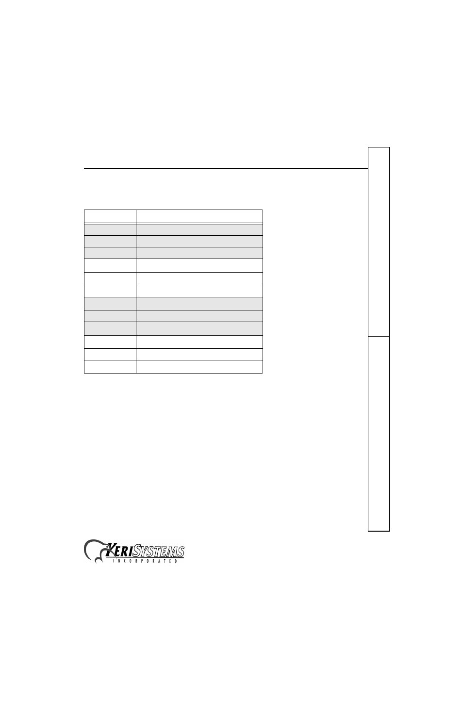
Inputs Table
Please refer to Figure 4 on page 4 for output relay wiring locations.
•
See page 10 for a sample Door Status Switch Input drawing.
•
See page 10 for a sample Request to Exit (RTE) Input drawing.
•
See page 10 for a sample Auxiliary RTE Input drawing.
•
See page 11 for a sample General Purpose Input drawing.
Table 3: Inputs
TB-8/TB-9 Inputs
Description
TB-8 – Pin 1
door status switch input – normally closed
TB-8 – Pin 2
common/ground
TB-8 – Pin 3
RTE input – normally open
TB-8 – Pin 4
GPI 3 input
a
/ AUX RTE-B
b
input – normally open
a. General Purpose inputs can accept either a normally closed or
normally open signal. The type of signal depends upon the type
of input device. The Doors software is then programmed to
accept that type of input.
b. The Auxiliary RTE input feature is not available in 16-bit Doors
software applications.
TB-8 – Pin 5
common/ground
TB-8 – Pin 6
GPI 4 input
a
TB-9 – Pin 1
GPI 5 input
a
TB-9 – Pin 2
common/ground
TB-9 – Pin 3
GPI 6 input
a
TB-9 – Pin 4
GPI 7 input
a
TB-9 – Pin 5
common/ground
TB-9 – Pin 6
GPI 8 input
a