Creating a g-link network, Installation ~ hardware setup – ClearOne AP10 User Manual
Page 12
Installation
~ Hardware Setup
8
Technical Services Group ~ 1-800-283-5936 (USA) ~ 1-801-974-3760
5.
Wire the AP10 to the AP800 using the provided three-terminal Phoenix
push-on connectors. These connectors are designed for easy wiring; simply
insert the desired wire into the appropriate connector opening and tighten
down the top screw.
•
Transmit Input Audio connected to the Transmit Input [D] will be sent
down the telephone line.
•
Receive Output Audio from the telephone participant is passed to
Receive Output [E].
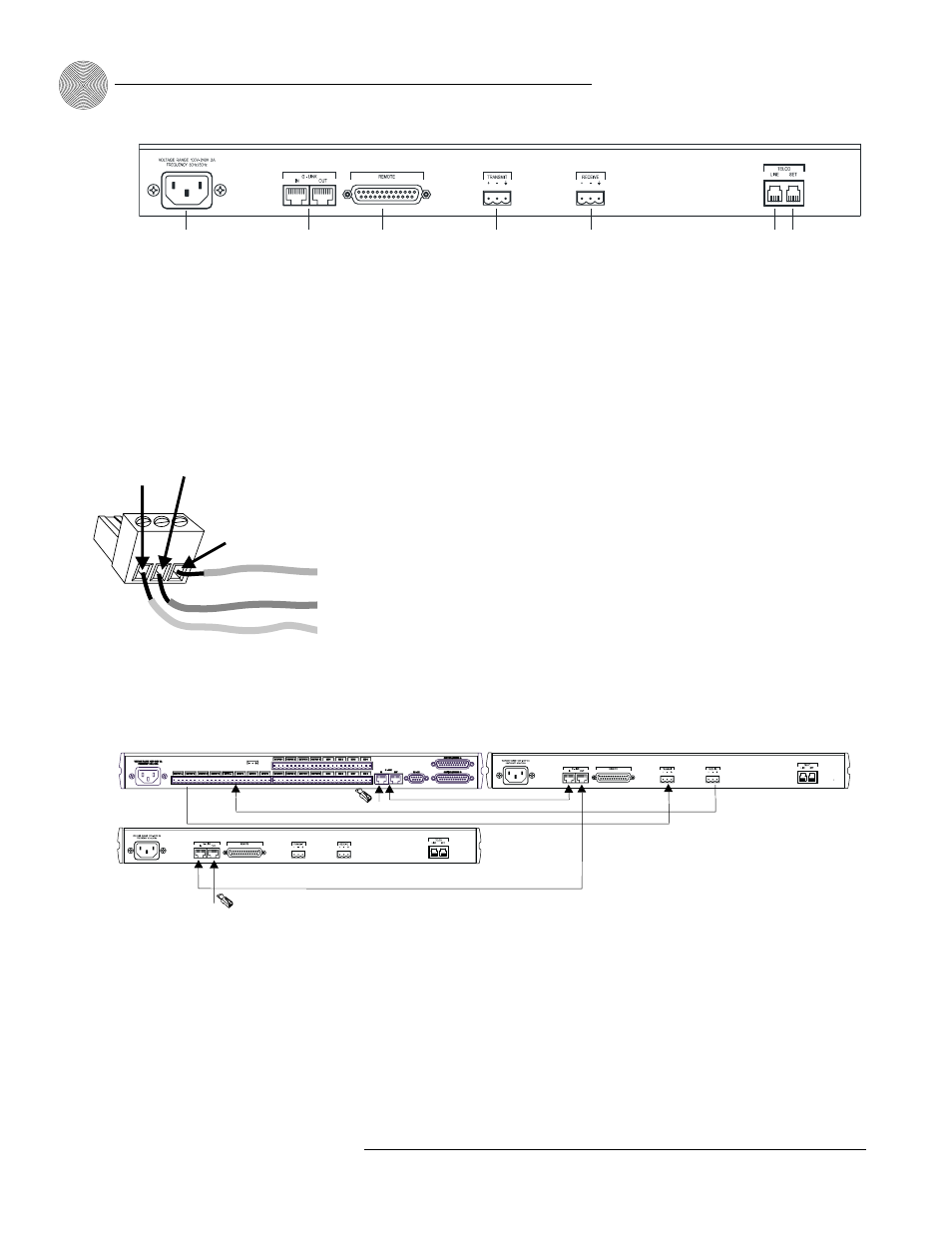
Creating a G-Link network
1.
Place the AP units in their proper locations. The back-panel G-Link In and
G-Link Out [B] connectors are designed for setting up your G-Link network.
G-Link connections between AP units are connected in daisy-chain fashion
using category five twisted-pair cable.
2.
The first ClearOne unit in the chain must have the G-Link In connector
terminated with a G-Link terminator (provided).
3.
The first ClearOne unit’s G-Link Out connector is then attached to the
G-Link In connector on the next unit in the chain. At the end of the network,
the final unit must have the G-Link Out connector terminated with a G-Link
terminator as well.
A G-Link network will allow interconnection of up to 16 AP10s and eight AP800s.
If the AP units are stacked vertically, connect them using the short RJ-45 jumper
(provided). If networking over longer distances (up to 20 feet/ 6.1 meters between
units), use Cat 5 twisted-pair (10BaseT LAN) cable.
A
B
C
D
E
F G
Figure 2.2. AP10 rear panel connectors
The three terminals in
the Phoenix connector
correspond with the back-
panel audio contacts (from left to
right): +(positive), –(negative), and
(ground).
✍
Figure 2.3. Phoenix push-on connector
+
–
Ground
Negative
Positive
AP800
AP 10
G-Link
Terminator
G-Link
Terminator
AP 10
G-Link
G-Link
Audio: Transmit and Receive
Figure 2.4. G-Link connection block diagram