Chapter 2: installation, Hardware setup connect the unit – ClearOne AP10 User Manual
Page 11
Technical Services Group ~ 1-800-283-5936 (USA) ~ 1-801-974-3760
The AP10 is designed for easy installation and set-up. All connections are made
through rear-panel connectors. This section provides instructions on installing the
units in the rack and making initial connections, creating a G-Link network, and
assigning device ID numbers.
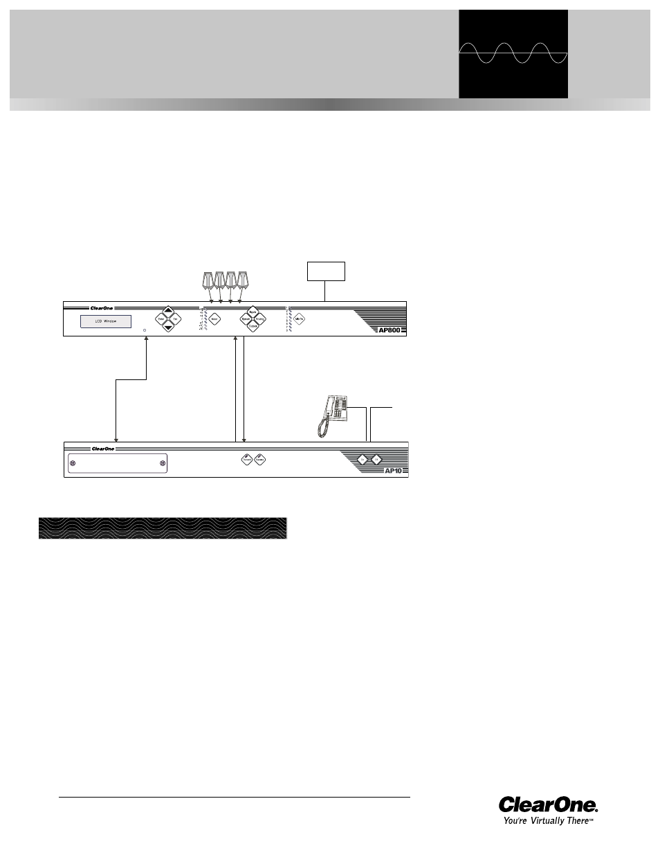
The diagram below illustrates the typical connections that are made when
adding an AP10 to an AP800.
CHAPTER 2: Installation
AP10
AP800
Telephone set
(optional)
Transmit
Input
Receive
Output
Microphones
Inputs
Touch panel
controller
G-Link connection
Line
Figure 2.1. System diagram
Hardware Setup
Connect the unit
Refer to the rear-panel drawing in Figure 2.2 on the following page. Each connector
is numbered for easy identification.
1.
Place the unit in the rack and attach it securely. AP10 models are designed
for installation in a standard 19-inch equipment rack.
2.
Connect your telephone line from the wall jack to the RJ-11C Line jack [F].
3.
Plug your telephone set into the RJ-11C Set jack [G].
4.
If you are using a custom controller for control and hybrid status, plug it
into the DB-25 Remote connector [C].