Specifications, Appendix b – Conair WSB User Manual
Page 103
One Conair Drive
●
Pittsburgh, PA 15202
●
412-312-6000
●
FAX 412-312-6227
●
www.conairnet.com
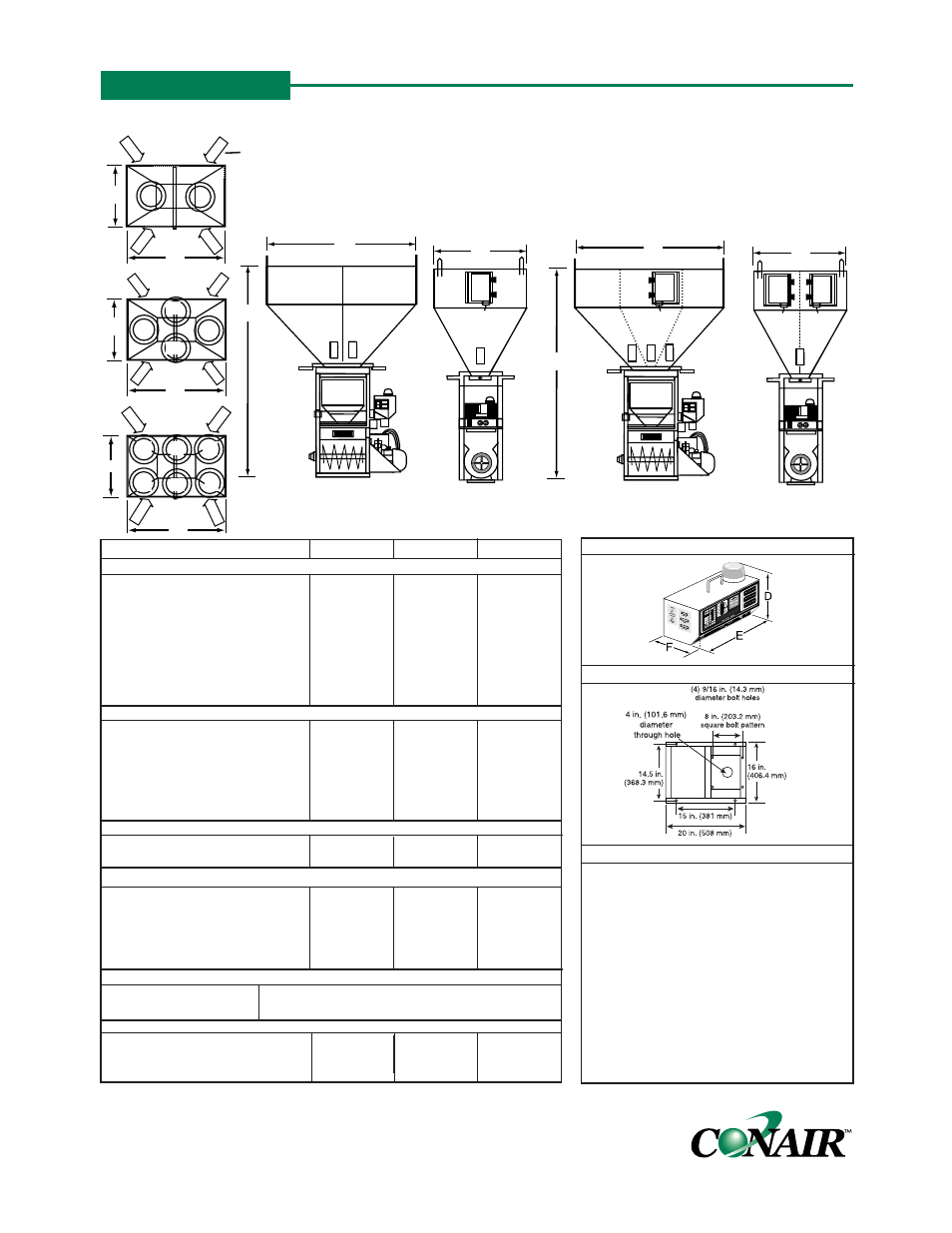
MODELS
GB920
GB940
GB960
Performance characteristics
Batch size lbs {g}
19.8 {9000}
19.8 {9000}
19.8 {9000}
Maximum throughput lbs/hr
{kg/hr}*
5200 {2359}
3300 {1497}
2124 {965}
Bin capacity - main ingredient
ft
3
{liter}
8.5 {240.7}
6.7 {189.7}
3.6 {102.9}
Bin capacity - minor ingredient
ft
3
{liter}
NA
3.6 {107.6}
3.6 {107.6}
Maximum number of materials
6
8
10
Number of discharge valves
2
4
6
Number of additive feeders
up to 4
up to 4
up to 4
Control software (# of components)
4 or 12
4 or 12
12
Dimensions inches {mm}
A - Height above mounting plate
†
74 {1880.7}
74 {1880.7}
74 {1880.7}
B - Width
‡
56 {1421.4}
56 {1421.4}
56 {1421.4}
C - Depth
‡
34 {863.6}
34 {863.6}
34 {863.6}
D - Controller height
11.25 {285.75}
11.25 {285.75}
11.25 {285.75}
E - Controller width
12.25 {311.15}
12.25 {311.15}
12.25 {311.15}
F - Controller depth
8.19 {208.03}
8.19 {208.03}
8.19 {208.03}
Weight lbs {kg}
Installed
480 {218}
480 {218}
480 {218}
Shipping
600 {272.2}
600 {272.2}
600 {272.2}
Voltage Running load amps
§
120V/1 phase/60 hz (control and mixer)
8.5
8.5
8.5
220V/1 phase/60 hz (control and mixer)
4.25
4.25
4.25
220V/1 phase/50 hz (control)
0.15
0.15
0.15
220V/3 phase/50 hz (mixer)
2.2
2.2
2.2
400V/3 phase/50 hz (mixer)
1.1
1.1
1.1
Compressed air requirements
Discharge valves
80 psi @ 0.2 ft
3
/min {5.5 bars @ 0.09 liters/sec}; 1/4 in. NPT fitting
Compressed air feeder
40 psi @ 2.0 ft
3
/min {2.8 bars @ 0.94 liters/sec}; 1/4 in. NPT fitting
Maximum loader sizes **
Number of 20 inch loaders
2
2
3
Number of 15 inch loaders
2
4
6
GRAVIMETRIC BATCH BLENDERS
AutoWeigh GB900 Series Models
MOUNTING INTERFACE
SPECIFICATION NOTES:
* Maximum throughput rates are based on 35 lbft
3
pelletized material and using all dispense valves.
Use of feeders for minor ingredients will reduce
this rate. Refer to the selection guide for more
specific throughput information.
† The optional flow control valve will add 6.5 in. {165
mm} to the total height. We recommend using the
flow control valve when mounting the blender to a
stand, surge bin or hopper.
‡ Feeders will increase depth dimensions. Please
refer to feeder specification.
§ Each auger feeder requires an additional 1 amp @
120V or 0.5 amp @ 240V.
** Maximum loader sizes may be used only when the
loader is adjacent to loaders of a smaller diameter.
SPECIFICATIONS
TPBS013/1199
IBO4
CONTROL
FEEDER LOCATIONS
2
1
D
C
B
A
B
C
GB920
2
1
D
C
B
A
B
C
GB940
A
B
C
GB960
4
3
8
1
7
2
4
3
A
B
C
FRONT VIEW
GB920
SIDE VIEW
GB920/GB940
A
B
C
FRONT VIEW
GB940/GB960
SIDE VIEW
GB960
B
C
D
NOTE: Any one of the
feeders (A,B,C or D)can be
designated position 5 or 6.
APPENDIX B