Carrier 38AUQ User Manual
Page 23
23
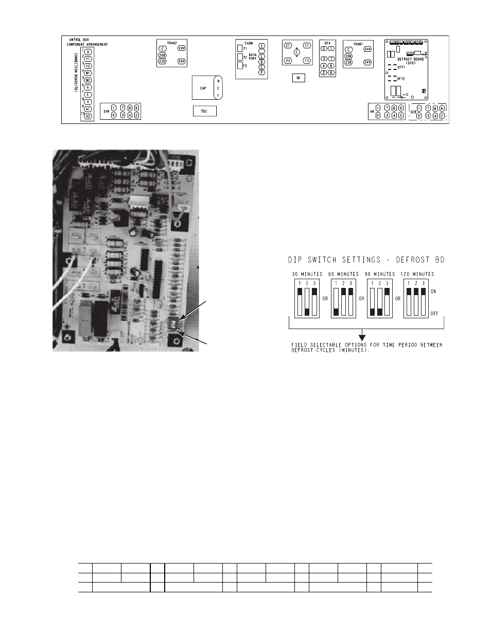
Fig. 21 — Defrost Control Board (DFB) Location
Fig. 22 — Defrost Control Board (DFB) Arrangement
Reversing valve control
The DFB has two outputs for unit reversing valve control. Op-
eration of the reversing valves is based on internal logic; this
application does not use an “O” or “B” signal to determine re-
versing valve position. Reversing valves are energized during
the Cooling stages and de-energized during Heating cycles.
Once energized at the start of a Cooling stage, the reversing
valve will remain energized until the next Heating cycle de-
mand is received. Once de-energized at the start of a Heating
cycle, the reversing valves will remain de-energized until the
next Cooling stage is initiated.
Compressor control
The DFB receives inputs indicating Stage 1 Cooling and Stage
1 Heating from the space thermostat or unit control system
(PremierLink); it generates commands to start compressors
with or without reversing valve operation to produce Stage 1
Cooling (one compressor), or Stage 1 Heating (both compres-
sors run).
Defrost
The defrost control mode is a time/temperature sequence.
There are two time components: The continuous run period
and the test/defrost cycle period. The temperature component
is provided by the defrost thermostat (DFT1) mounted on the
outdoor coil.
The continuous run period is a fixed time period between the
end of the last defrost cycle (or start of the current Heating cy-
cle) during which no defrost will be permitted. This period can
be set at 30, 60, 90 or 120 minutes by changing the positions of
DIP switches SW1 and SW2 (see Fig. 23 and Table 13). The
default run period is 60 minutes.
Fig. 23 — DIP Switch Settings — Defrost Board
At the end of the continuous run period, the defrost control will
test for a need to defrost. On unit sizes 04-07 (single compres-
sor designs), DFT1 controls the start and termination of the de-
frost cycle. If DFT1 is still open, the defrost test/run window is
closed and the control repeats the continuous run period. If
DFT1 is closed, the defrost cycle is initiated. The defrost period
will end when DFT1 opens (indicating the outdoor coil has
been cleared of frost and ice) or a 10 minute elapsed period ex-
pires, whichever comes first.
At the end of the unit defrost cycle, the unit will be returned to
Heating cycle for a full continuous run period.
If the space heating load is satisfied and compressor operation
is terminated, the defrost control will remember where the run
period was interrupted. On restart in Heating, the defrost con-
trol will resume unit operation at the point in the run period
where it was last operating.
Table 13 —Dip Switch Position
DIP
Switches
Speed-Up
Jumpers
Switch No.
1
2
1
2
1
2
1
2
3
1
■
1
■
1
1
■
■
1
On
0
■
0
■
0
■
■
0
0
■
Off
30 minutes
60 minutes
90 minutes
120 minutes
Fan Delay