Juniper Systems TK6000 I/O Module User Manual
I/o module
TEL:
435.753.1881
FAX:
435.753.1896
WEB:
www.junipersys.com
The following items should be included in
the replacement kit:
▪ Instructions
▪ I/O Module
▪ Screwdriver
P/N:
20389-03 12/13
1132 W. 1700 N. Logan, UT 84321
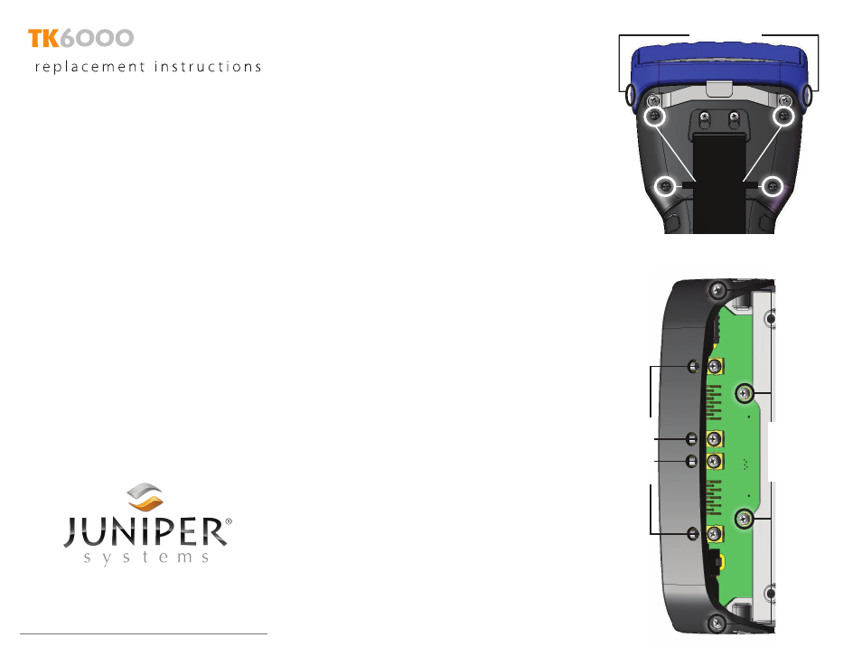
Complete the following steps to replace the
I/O module on the TK6000.
Note: There are no replacement screws for the
bumper in the kit.
1. Remove bumper screws and case back screws.
2. Remove the four 4 mm screws that are easily
accessible on the I/O module. There are two at
the bottom of the board and two on either side
set in the bridge of plastic that covers part of
the I/O board.
3. Remove the four 5 mm screws that are set
under the plastic bridge. There are four holes in
the bridge that allow the provided screwdriver
to fit through the plastic to reach the screws.
4. Hold the module by the plastic bridge and pull
it off.
5. Take the new module from the kit and place
it in the TK6000. It should settle in without
needing any force.
6. Attach the four 4 mm screws that come with
the kit. Tighten them snugly in place.
CAUTION: It is possible to over-tighten the
screws and strip the screw hole threads. To
avoid this, tighten the screws using the Phillips
end of the included screwdriver. If the threads
are accidentally stripped, contact a service
center to schedule a repair.
Note: The screw heads can be pushed onto the
screwdriver which will hold them in place.
7. Carefully place the four 5 mm screws through
the holes in the bridge and tighten them snugly
in place.
8. Reattach the case back and tighten the four
screws.
9. Replace the top bumper with the two screws on
either side.
10. Test the connections of the newly replaced I/O
module.
Bumper Screws
Case Back Screws
5
mm
Screws
4
mm
Screws
▪ 4mm screws (4)
▪ 5mm screws (4)
I/O Module