Installation, Wiring – Interlogix 584509-W User Manual
Page 2
2
Wireless ShatterPro Acoustic Sensor Installation Instructions
Plate, tempered, laminated, and wired glass
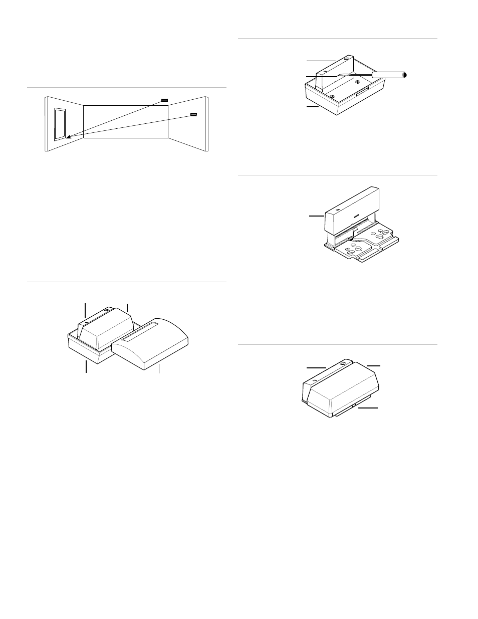
Mounted on the ceiling or the opposite or adjoining wall,
(Figure 1 below) maximum range is 25 ft. (7.6 m).
Figure 1: Maxim um coverage range
Installation
The sensor has two mounting options.
Sensor base housing
You can place the wireless transmitter inside the sensor’s base
housing (Figure 2 below). For some large transmitters, it will
be necessary to remove the transmitter board from its housing.
Figure 2: Sensor base housing
Transmitter bracket
For large transmitters that do not fit into the sensor base, or for
a smaller appearance with a standard size transmitter, use the
transmitter bracket.
To mount the sensor on the transmitter bracket, do the
following:
1. To remove the sensor module from the base, depress the
catch in the center of the sensor module (Figure 3 below)
and rock the module up off the posts.
Figure 3: Rem oving the sensor module
2. Snap the sensor module unto the bracket (Figure 4
below).
Figure 4: Snapping the sensor module onto the bracket
3. Run the wires to the transmitter and attach the transmitter
to the bracket (Figure 5 below). Use the punched double-
stick tape provide
d to hold the wire in the bracket’s wire
channel, and to hold the transmitter to the bracket.
Figure 5: Attaching the transmitter to the bracket
4. Mount the sensor/transmitter/bracket assembly. If the
transmitter’s mounting holes don’t fit the bracket’s hole
pattern, you will have to mount the bracket to the wall or
ceiling before attaching the transmitter.
Wiring
All wiring must conform to the National Electric Code (NEC)
and/or local codes having jurisdiction.
Sensor module
Transmitter
Base
Lid
Sensor module
Transmitter
Bracket
Sensor m odule
Sensor module
Catch
Base
25 ft. (7.6 m )
25 ft. (7.6 m )