Interlogix AP669 User Manual
Ap669 ceiling mount detector, Installation instructions, Selecting a mounting location
Selecting a Mounting location
Install the detector so that the expected movement of an intruder will be
across the fields of view. This is the direction best suited for PIR
detectors.
Avoid possible false alarm sources such as:
•
Direct sunlight onto the detector.
•
Heat/cold sources in a field of view (heaters, air conditioning,
radiators, etc.).
•
Moving objects in the field of view (fans, pets, etc.).
Increasing mounting heights beyond the specified range will reduce
sensitivity.
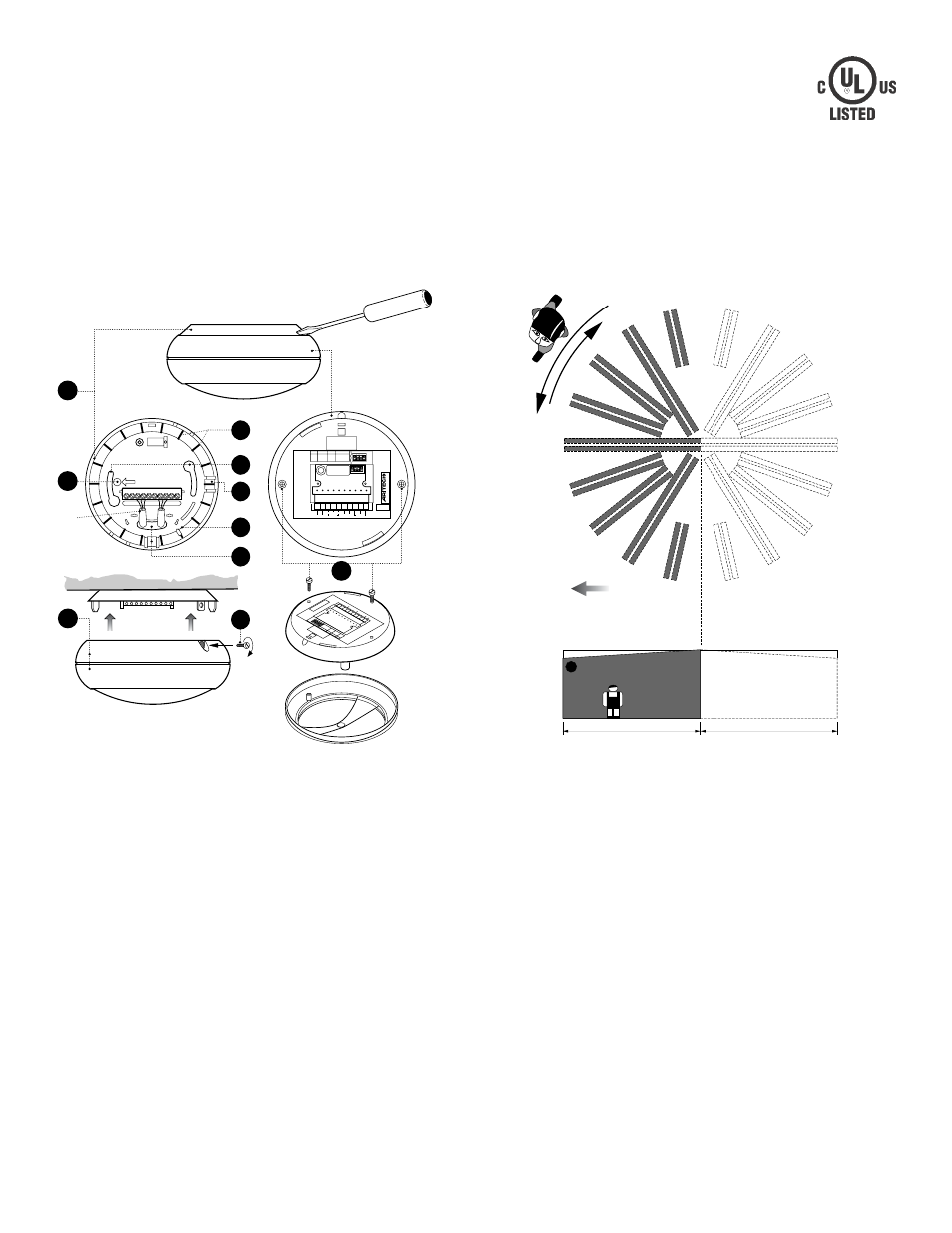
Mounting Instructions
•
Lift off mounting plate (1) as shown in Figure 1. Fasten the
mounting plate to the ceiling in the required position using mounting
holes (2).
The detection pattern can be adjusted by up to ±15° (max
30°) by rotation of the mounting plate prior to tightening the
screws.
•
Strip outer jacket approximately 2 inches (50mm) and pull it through
the cable entry hole (3) and strain relief.
•
Wire the detector and select the appropriate processing
options as shown in Figure 3 and replace the sensor module (6).
•
To mount the sensor module to the mounting plate use the
screw (7) which is placed for transport in the mounting plate.
The curtain directions 1-9 clockwise (8), are indicated in the
mounting plate. (Curtain number 5 is the center curtain.)
AP669
Ceiling Mount Detector
Installation Instructions
Figure 2
Figure 1
1
2
3
4
5
6
7
8
9
10
MADE
IN
THE
NETHERLANDS
EV669
OPERATION:
7 ñ15V
CURRENT:
6 mA NOM.
ALARM:
11 mA MAX
O
N
1
2
3
4
O
N
1
2
3
4
1 2 3 4 5 6 7 8 9 10
ñ
+
ALARM
NC C NO
TAMPER
SPARE
1
4
2
8
3
3
5
7
7
6
2 in.
1
2
3
4
5
6
7
8
9
1
2
3
4
5
6
7
8
9
1
2
3
4
5
6
7
8
9
1
2
3
4
5
6
7
8
9
5
30'
30'
An arrow inside
the mounting plate &
sensor module indicates
the always active direction.
Shaded area shunted when
switch 3 is ìONî position.