Interlogix 60-880-95 User Manual
Installation instructions, Product summary, Installation guidelines
1
6HQWURO,7, $3:
:LUHOHVV 3,5 0RWLRQ
6HQVRU
ITI Part No. 60-880-95
Installation Instructions
Document Number: 466-1851 Rev. B
July 2001
Product Summary
A motion sensor (passive-infrared or PIR) detects move-
ment by sensing the infrared energy emitted from a body as
it moves across its field of view. When this motion is
detected, the sensor transmits an alarm signal.
Install motion sensors to protect areas where door/window
sensors are impractical or not needed. For example, use a
motion sensor to protect large areas or open floor plans.
Motion sensors can also provide backup protection in areas
where door/window sensors exist.
This wireless motion sensor includes the following features:
Field-selectable coverage area; 33 or 50 feet
Field-selectable sensitivity modes; 2-pulse or 4-pulse
135-second transmitter lockout time after an alarm that
helps extend battery life
Cover-activated tamper
Supervisory signal transmitted every 64 minutes to the
control panel
Sensor low battery reports (trouble) to the control panel
Included with the sensor is a thin cardboard undercrawl
mask and snap-in plastic masks (installed at the factory).
Self-adhesive masking strips are also included.
Installation Guidelines
If possible, locate sensors within 100 feet of the panel.
While a transmitter may have an open-air range of 500
feet or more, the installation site can have a significant
effect on transmitter range. Changing the sensor loca-
tion may help overcome adverse wireless conditions.
Mount the sensor permanently on a flat wall or in a cor-
ner. Do not set it on a shelf.
For installations without pets, the required mounting
height is 7 1/2 feet.
Mount the motion sensor on an insulated, outside wall
facing in.
Mount the motion sensor on a rigid surface which is
free from vibrations.
Position the sensor so it faces a solid reference point,
like a wall.
Do not aim the sensor at windows, fireplaces, air condi-
tioners, heaters/heating vents, or place it in direct sun-
light.
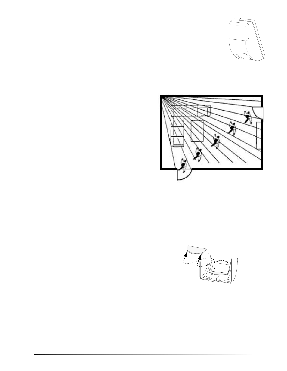
Position the sensor to protect an area where intruders
are most likely to walk across the detection pattern (see
Figure 1).
Figure 1. Overhead View of Detection Pattern
Do not mount the sensor near duct work or other large
metallic surfaces which may affect the RF signals (see
“Final Testing” on page 4). Actual acceptable transmit-
ter range should be verified for each installation.
Windows should be closed in any area which has an
armed motion sensor.
The cardboard undercrawl mask installed at the factory
(see Figure 2) blocks coverage within 5 feet of the sen-
sor.
Figure 2. Cardboard Undercrawl Mask Location
1RWH
The cardboard undercrawl mask should remain
installed when sensor jumper J1 is set to the BI posi-
tion. See the section “Setting the Sensor Coverage
Area and Sensitivity” for complete information on sen-
sor jumper settings.
8362G04B.DS4
Person walking across detection path