Interlogix AP750-ID User Manual
Ap750-id installation instructions, Description, Parts included
AP750-ID Installation Instructions
Description
The AP750-ID is an addressable PIR device that interfaces
with the PinPoint
®
system. This system provides flexible and
reliable two-way communication between the device and the
controller.
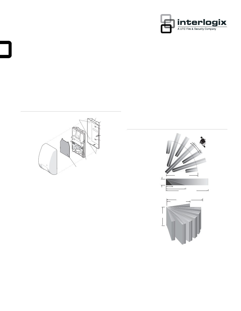
Figure 1: Exploded view
1 - Corner mounting knockouts
2 - Base indent
3 - Wall mounting bracket
4 - Flat wall mounting knockout
5 - Cable entry
6 - Tamper actuator
7 - Flat wall mounting knockout
8 - Tabs
9 - Wiring access
10 - Circuit board
1
2
3
4
5
6
7
8
9
10
Parts included
• PIR
detector
•
Two plastic masks
•
One screw to secure the to the wall mounting bracket
• Wall
mounting
bracket
•
Sheet of adhesive masking labels
• Cardboard
undercrawl
window
mask
Selecting a location
Mount the unit:
•
On a rigid vibration-free surface.
•
6 to 10 feet (1.8 to 3m) high, but at least 6 inches (15cm)
from the ceiling.
•
So the expected movement of an intruder is across the
fields of the detection pattern. See Figure 2 below.
Figure 2: Detection pattern
10.0 ft.(3.0m) maximum
8.0 ft.(2.4m) nominal
6.0 ft.(1.8m) minimum
8.0 ft.(2.4m)
25.0 ft.(7.6m)
50.0 ft.(15.2m)
50.0 ft.(15.2m)
10.0 ft.(3.0m)
33.0 ft.(10.1m)
33.0 ft.(10.1m)
Do not locate the unit:
•
On a surface exposed to moisture.
•
Where it may be exposed to false alarm sources such as:
direct sunlight, heat sources (heater, radiators, etc.) in the
field of view, strong air drafts (fans, air conditioner, etc.).
P/N 1036045 • REV C • 16MAY11
1