Interlogix NX-592E User Manual
Page 3
NX-592E NetworX Cellular Module Installation Sheet
To wire the module:
1. Remove AC panel power and disconnect the backup
battery.
2. Wire the module to the panel bus and power terminals
(see Figure 3 below).
Figure 3: Wiring connections
POS COM DATA
KP POS KP COM KP DATA
Gateway
Panel
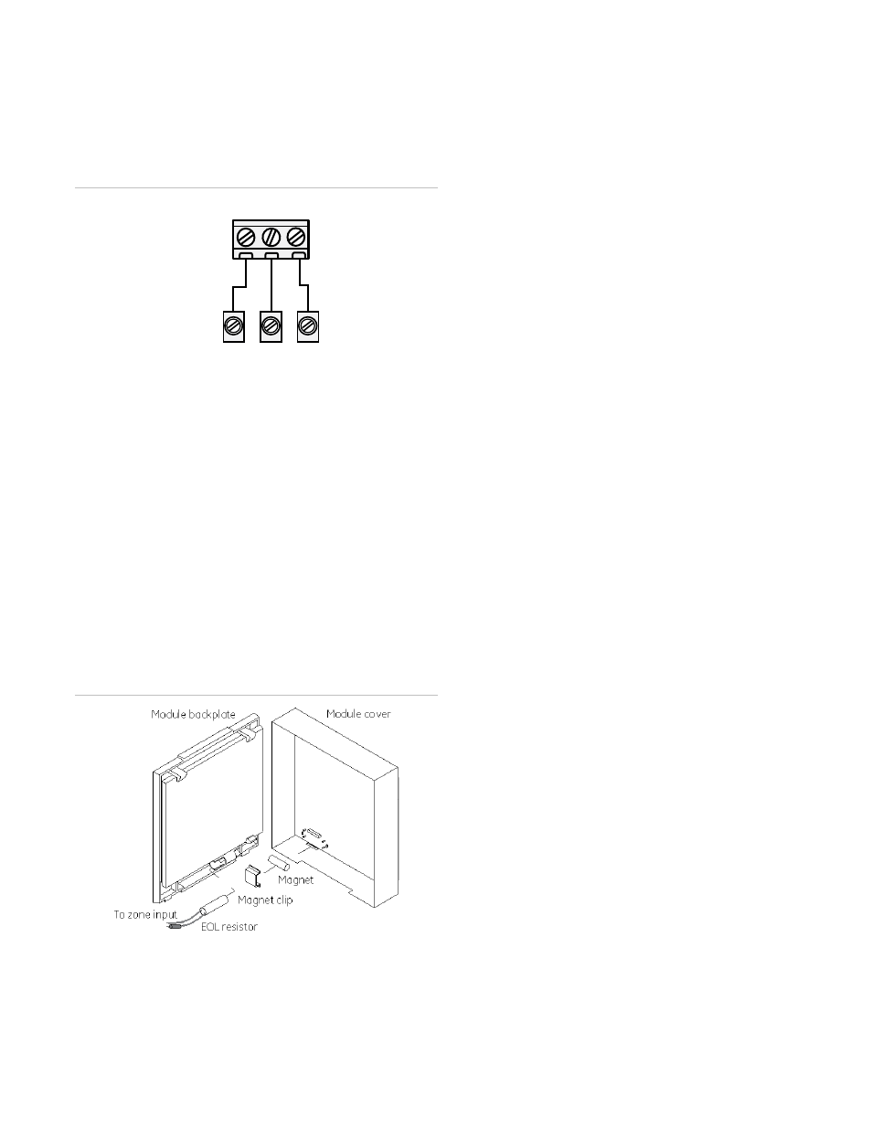
Case tamper switch (optional)
If the module is easily accessible, you can add case tamper
detection to activate an alarm or trouble (depending on panel
programming) when the cover is removed.
To install the tamper switch:
1. Slide the reed switch into the plastic holder on the module
back plate.
2. Connect a UL-Listed reed switch (with EOL resistor) to
any unused hardwired input on the panel.
3. Insert the magnet into the nibs on the top cover and press
the magnet clip down over the magnet until it clicks into
place into the cover.
Figure 4: Case tamper switch
Power up
You will need to power up the module and panel to start
communication between them.
To power up:
1. Verify that all wiring between the panel and module is
correct.
2. Connect the backup battery and restore AC power to the
panel.
3. Verify that radio status LED 1 is not flashing any errors
(see Cellular Status LEDs on page 4). Also, verify that
LED 4 is flashing a cellular signal level of two or higher.
Otherwise, relocate the module. If LED 1 and LED 4 are
not flashing, and LED 2 and LED 3 are flashing together,
the module is in Power Save mode and the battery needs
to be charged.
4. Perform a manual phone test by pressing *44 while the
system is disarmed (Make sure that panel’s Location 37,
Segment 2, Bit 7 is set).
Note: if Location 37, Segment 2, Bit 6 is set,
performing the phone test will trigger the local siren.
To avoid triggering the siren when performing the
phone test, make sure Bit 6 is OFF.
The panel will not show any indication that the phone test
signal has been sent. You can check the radio status LEDs L3
and L4: L4 should be blinking on for 2 seconds and off for 2
seconds. L3 will blink once briefly as soon as you press *44. If
the account is reporting to a Central Station, wait for a minute
and check with the Central Station to see if the phone test
signal was received correctly. The phone test is also used by
Alarm.com to set the module's parameters the first time the
module is powered up. It ensures that Alarm.com will receive
the sensors list and any other information required for proper
signaling.
Enrolling the module
The NetworX control panels automatically find and store in
memory the presence of all keypads, zone expanders, wireless
receivers, output modules, and any other device on the keypad
bus, allowing these devices to be supervised by the control
panel. To enroll the devices, enter Program Mode (refer to your
control panel documentation). When you exit Program Mode,
the control panel automatically enrolls the devices. This
process takes about 12 seconds. During this time, the Service
LED will illuminate and User codes will not be accepted. Once
a module is enrolled, if it is not detected by the control panel,
the Service LED will illuminate. When initially powering up, the
control panel automatically performs the device enrollment
process.
Programming using the keypad
The wireless gateway needs to know the address of at least
one of the LCD keypads. Some commands, such as getting
the zone names for display on the website, will not work if the
keypad address is not known. By default, the wireless gateway
assumes a keypad address of 192 (keypad 1, partition 1). If
your LCD keypad is programmed differently (press *94 +