Interlogix NX-592E User Manual
Page 2
2
NX-592E NetworX Cellular Module Installation Sheet
Installation Tips
Use the following tips to ensure success with the Alarm.com
NetworX cellular module:
•
Make sure you create the customer account on the
Alarm.com dealer website at least 24 hours before
installation.
•
Use the Cellular Status LEDs on the module to check the
signal strength before you permanently mount the module.
•
NetworX panels support a maximum of one wireless
gateway per system.
•
Do a manual phone test to initiate communication (see
“Power up” on page 3).
Installation
The module draws a maximum of 65 mA (continuous) from the
panel in power save mode, and 100 mA (continuous) from the
panel in idle and connected modes. The module can draw up
to 1600 mA (instantaneous peaks) from the panel. Do not
exceed the panel total output power when using panel power
for bus devices and hardwired sensors (refer to the panel
documentation).
Use three-conductor, 22 or 18 gauge stranded wire to connect
the module to the panel. Table 2 below shows the maximum
wire length for each gauge.
Table 2: Maximum wire length
Gauge
Maximum wire length to panel
22 gauge
40 ft. (12.2 m)
18 gauge
90 ft. (27.4 m)
You will need the following tools and supplies to install the
module:
•
Small blade and Phillips screwdrivers
•
Drill and bits for screws and/or anchors
•
Wire cutter/stripper
•
Three-conductor, 22-gauge or larger stranded wire
•
#6 pan head screws (4 included)
•
Wall anchors (four included)
•
3.3-Kohm EOL resistors (included with main NX panel)
Use the following guidelines to choose a location for the
module:
•
Check the signal strength before choosing a location. Do a
walking signal strength test by powering the module off the
battery directly (connect the COM and POS terminals).
After 2 minutes, cellular status LED 4 will flash between
one and five times, where 5 indicates strongest signal
level. We recommend a signal level of two or higher.
•
Do not the mount the module inside the panel’s metal
enclosure.
•
Avoid mounting the module in areas with excessive metal
or electrical wiring, such as furnace or utility rooms.
•
Locate the module near an outside wall, preferably on an
upper level.
•
For homes or businesses located in canyons or with hills
nearby, it is necessary to place the antenna higher in the
building.
Caution:
You must be free of static electricity before handling
electronic components. Touch a grounded metal surface
before touching the circuit board.
To mount the module:
1. Press down on the top of the enclosure cover, remove it,
and set it aside.
2. Snap the antenna onto the antenna connector (see
Figure 1 on page 1). To connect the antenna, place one of
your thumbs or fingers behind the antenna connector.
With your other hand, press the end of the micro miniature
coaxial connector (MMCX) into the antenna connector
until you hear a slight click.
3. Place the back plate on the wall at the desired mounting
location, check for level, and mark the three mounting
holes and the wire access area (see Figure 1 on page 1).
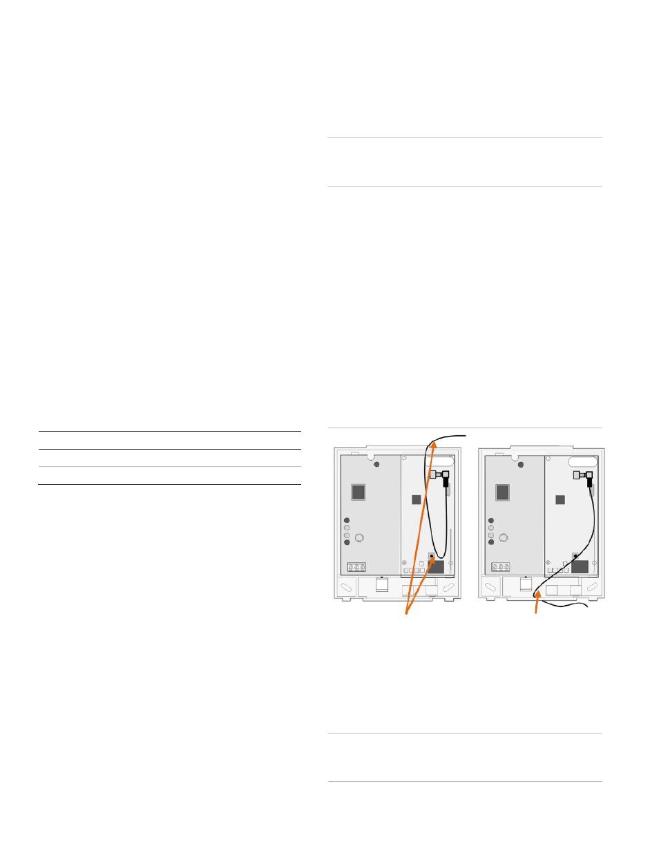
4. To avoid placing unnecessary strain on the antenna
connector, which can damage the module, use either of
the following orientations shown in Figure 2.
Figure 2: Antenna Routing
5. Set the back plate aside and drill holes at the mounting
and wire access area locations.
6. Use wall anchors where studs are not present and secure
the back plate to the wall with the enclosed screws.
Wiring Connections
Caution:
To prevent damaging the panel or module, you must
remove panel AC power and disconnect the backup battery
before making or changing wiring connections.
Loop antenna and feed -OR-
back through top of module
Feed antenna through wire
access area and into wall