IC Realtime Specialty: 4-CH Mobile DVR User Manual
Page 81
81
6.2.6 Activate Pattern Function
In
X419H419H419H389H389H389H396H359H
Figure 6-6
X
input mode value in the No. blank, and click pattern button.
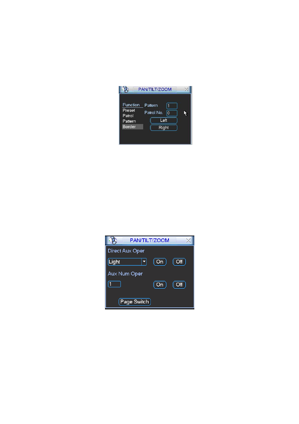
6.2.7 Border Setup
In
X420H420H420H390H390H390H397H360H
Figure 6-5
X
, click border button. The interface is shown as in
X421H421H421H391H391H391H398H361H
Figure 6-10
X
.
Please go to
X422H422H422H392H392H392H399H362H
Figure 6-2
X
, use direction arrows to select camera left limit, and then please go to
X423H423H423H393H393H393H400H363H
Figure 6-10
X
and click left limit button
Repeat the above procedures to set right limit.
Figure 6-10
6.2.8 Activate Border Function
In
X424H424H424H394H394H394H401H364H
Figure 6-6
X
, click auto scan button, the system begins auto scan. Correspondingly, the auto
scan button changes to stop button.
Click stop button to terminate scan operation.
6.2.9 Flip
In
X425H425H425H395H395H395H402H365H
Figure 6-6
X
, click page switch button, you can see an interface is shown as below. See
X426H426H426H396H396H396H403H366H
Figure
6-11
X
. Here you can set auxiliary function.
Click page switch button again, system goes back to
X427H427H427H397H397H397H404H367H
Figure 6-2
X
.
Figure 6-11