IC Realtime Specialty: 4-CH Mobile DVR User Manual
Page 29
29
3. How to connect PTZ decoder
a. Ensure the decoder has the same grounding with DVR, otherwise you may not control the PTZ.
Shielded twisted wire is recommended and the shielded layer is used to connect to the grounding.
b. Avoid high voltage. Ensure proper wiring and some thunder protection measures.
c. For too long signal wires, 120Ω should be parallel connected between A, B lines on the far end
to reduce reflection and guarantee the signal quality.
d. “485 A, B” of DVR cannot parallel connect with “485 port” of other device.
e. The voltage between of A,B lines of the decoder should be less than 5v.
4. Please make sure the front-end device has soundly earthed.
Improper grounding may result in chip damage.
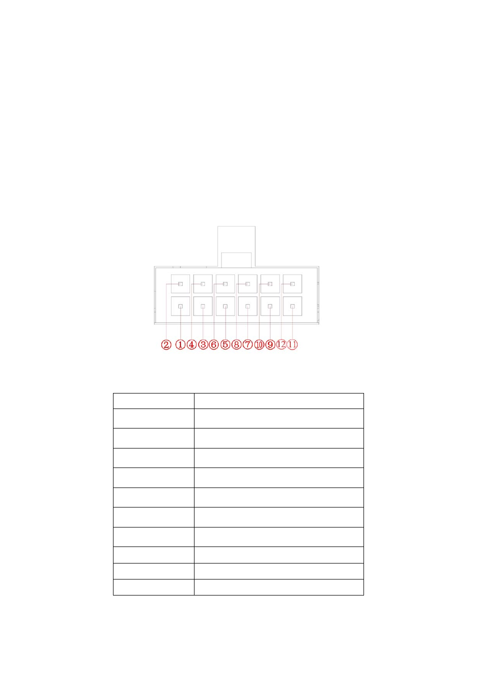
3.7.1 Alarm Input and Output Details
Alarm input and output interface is shown as in Figure 3-8.
Figure 3-8
Please refer to the following sheet for detail information.
SN Function
1
Alarm input 1(White cable)
Connect it to the left-turn signal cable.
2
Alarm input 2(White cable)
Connect it to the right-turn signal cable.
3
Alarm input 3(White cable)
Connect it to the reverse signal cable.
4
Alarm input 4(White cable)
Connect it to the stop signal cable.
5
Alarm input 5(White cable)
To be developed.
6
Alarm input 6(White cable)
To be developed.
7
Alarm input 7(White cable)
To be developed.
8
Alarm ground cable(Purple cable)
9/10
NO output 1(Yellow cable)
11/12
NO output 2(Yellow cable)
Bidirectional talk and RS485 port interface is shown as in Figure 3-9.