7 alarm input and output connection – IC Realtime Specialty: 4-CH Mobile DVR User Manual
Page 28
28
Figure 3-6
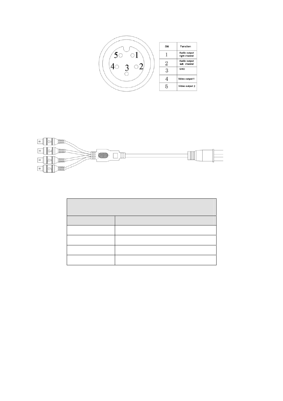
Audio/video output cable is shown as below. See Figure 3-7. You can use it when your monitor
port is general BNC port.
Figure 3-7
Please refer to the following sheet for detail information.
Audio/Video Output Cable (Aviation-level port 5p male
socket )
Socket
Color and Definition
1
Yellow BNC male port(Video output )
2
White BNC male port(Video output)
3
Black BNC male port(Audio output )
4
Red BNC male port(Audio output)
3.7 Alarm Input and Output Connection
There are two alarm input types for you to select: normal open (NO) and normal close (NC).
1. Alarm input
a. Please make sure alarm input mode is grounding alarm input.
b. Grounding signal is needed for alarm input.
c. When you are connecting two DVRs or you are connecting one DVR and one other device,
please use a relay to separate them,
2. Alarm output
The alarm output port should not be connected to high power load directly (It shall be less than
1A) to avoid high current which may result in relay damage. Please use the co contactor to
realize the connection between the alarm output port and the load.