IC Realtime Specialty: 4-CH Mobile DVR User Manual
Page 30
30
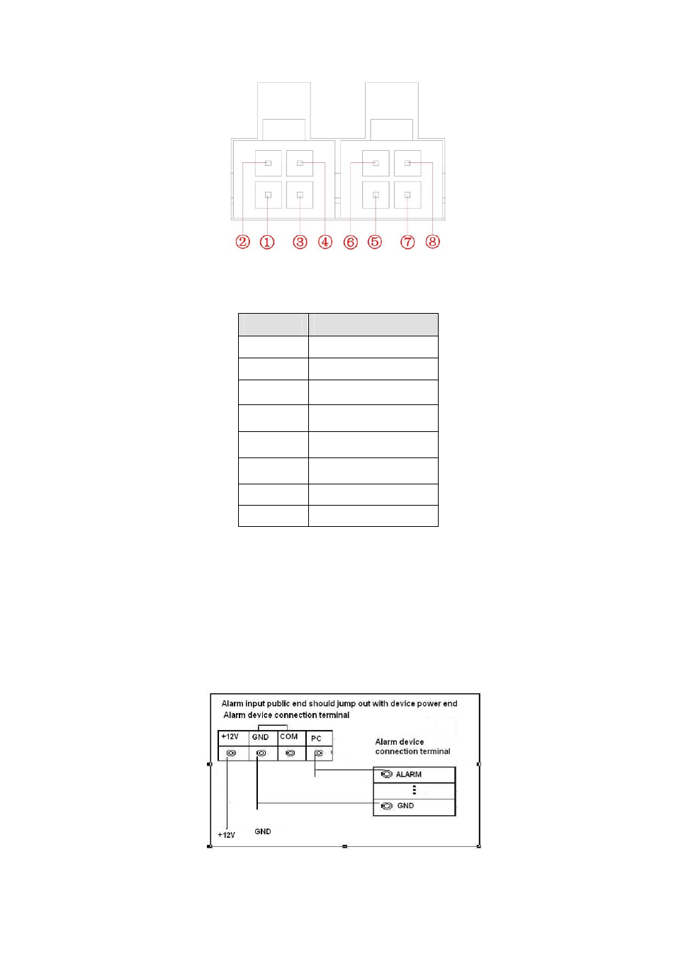
Figure 3-9
Please refer to the following sheet for detail information.
SN
Function
1 GND
2 Microphone
3 GND
4 Earphone
5
Power control
6
A cable
7 GND
8 B
cable
3.7.2 Alarm Input Port
Please refer to the following sheet for more information. See Figure 3-10.
z
4/8/16-ch grounding alarm inputs. (Normal open or Normal close type)
z
Please parallel connect COM end and GND end of the alarm detector (Provide external
power to the alarm detector).
z
Please parallel connect the Ground of the DVR and the ground of the alarm detector.
z
Please connect the NC port of the alarm sensor to the DVR alarm input(ALARM)
z
Use the same ground with that of DVR if you use external power to the alarm device.
Figure 3-10
See also other documents in the category IC Realtime Video surveillance systems:
- Max Series: 4/8/16 Channel D1 1.5U Standalone DVR (197 pages)
- Flex Series: 4-CH High Performance H.264E 2U DVR with DVD-RW (195 pages)
- Flex Series: 32-CH High Performance H.264E 2U DVR (180 pages)
- Flex Series: 64 Channel 2CIF 3U Standalone DVR (185 pages)
- Combo Series: 8 Channel DVR with built-in 10 LCD monitor (153 pages)
- Combo Series: 8 Channel DVR with built-in 19 LCD monitor (141 pages)
- Specialty: Interrogator DVR - a DVR for law enforcement (136 pages)
- Specialty: 4-CH H.264E CUBE REAL-TIME DVR with BUILT-IN 5.6 LCD (134 pages)
- H.264E Hybrid DVRs with 4-CH Analog + 4-CH IP (174 pages)
- 4/8 All Channel 720P Mini 1U HD-AVS DVR (173 pages)
- 1.3 Megapixel 720P Weather-proof IR HD-AVS Mini Dome Camera (18 pages)
- 1.3 Megapixel 720P Weather-proof IR HD-AVS Camera (12 pages)
- 1.3 Megapixel 720P Water-proof HD-AVS Camera (36 pages)
- 1.3 Megapixel 720P HD-AVS IR PTZ Dome Camera (38 pages)
- 2 Megapixel 1080P Weather-proof IR HD-AVS Camera (16 pages)
- 2 Megapixel 1080P Weather-proof IR HD-AVS Camera (16 pages)
- 4/8 H.264E HD SDI High Definition DVR (234 pages)
- 1080P (Full HD over coax) HD-SDI / HDcctv 20x Optical PTZ / IR (37 pages)
- 1080P Full HD HDcctv/HD-SDI Box CCD Camera (15 pages)
- HD-SDI High performance processor camera (19 pages)
- 1080P (Full HD over coax) HD-SDI / HDcctv 20x Optical PTZ (37 pages)
- 8/16/32 Channel 1.5U 8/16 PoE Network Video Recorder (151 pages)
- 4/8/16/32 Channel 2U Network Video Recorder (161 pages)
- 4/8/16/32 Channel 1U PoE Network Video Recorder (164 pages)
- 128 Channel Intel Core i5 Processor Super NVR (4 pages)
- 4 Channel Forensic Network Video Recorder (169 pages)
- 4 Channel PoE Mobile Network Video Recorder (158 pages)
- 1/2/4 Channel H.264 Network Video Server (100 pages)
- 7- inch Color Indoor Monitor (IHD7310) (15 pages)
- Villa Outdoor Station (IHC6260) (15 pages)
- 7- inch Color Indoor Monitor (IHD7210) (12 pages)
- PoE switch for Intercom System (IHS1030) (7 pages)
- 1.3 MegaPixels Aluminum Commercial Outdoor Station (IHXC1201) (28 pages)
- Professional 3-D DVR/PTZ Keyboard with Network Capability (34 pages)